12
Input assembly replacement continued:
Pull out | |
J4 | J3 |
- | + |
Input | Thru |
1 | 2 |
J3 | 2 | 1 | J4 |
| |||
+ | - | ||
|
|
|
Thru | Input |
|
Pull out
J3 | J4 |
+ | - |
Thru 2 | 1 Input |
3
4
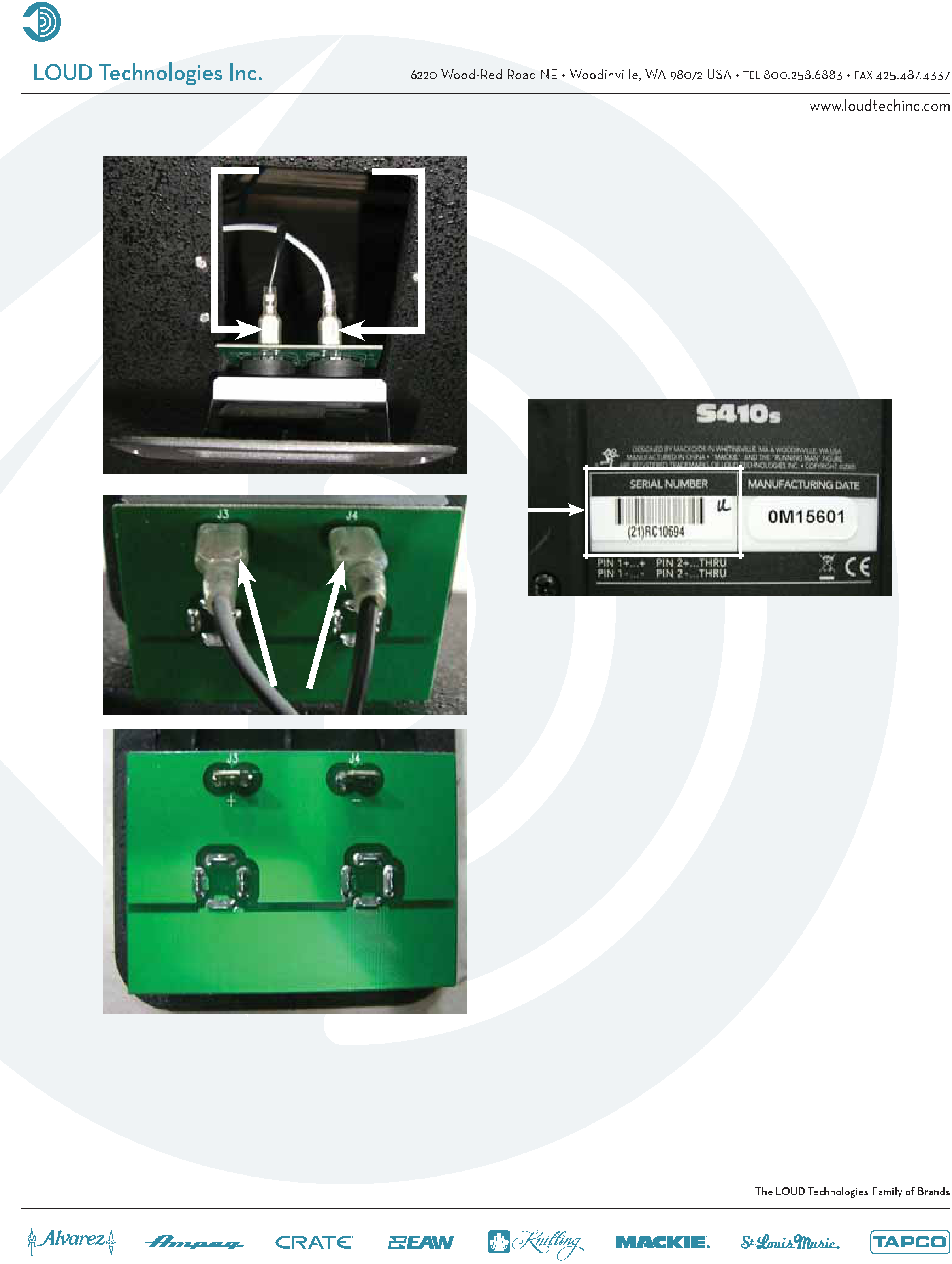
Two cables need to be removed from the input assembly PCB (as shown on the left): (1) the solid black cable attaches to the negative terminal (connection J4). This is for the input jack, and (2) the grey and black cable attaches to the positive terminal (connection J3). This is for the thru jack. Do not force cable removal or connection, although
Place the new input assembly (part #0011817) where the old one was. Follow the same steps as above, but backwards 3 to 1. Remove the serial number from the faulty input assembly (as shown
in the picture above) and place on the new input assembly. Power up the S410s and relish in the fact that you just replaced an input assembly. Hats off to you for a job well done!