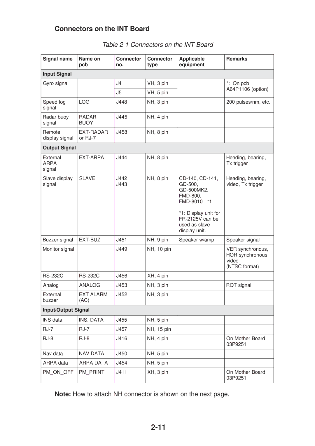
Connectors on the INT Board
Table 2-1 Connectors on the INT Board
Signal name | Name on | Connector | Connector | Applicable | Remarks |
| pcb | no. | type | equipment |
|
|
|
|
|
|
|
Input Signal |
|
|
|
|
|
|
|
|
|
|
|
Gyro signal |
| J4 | VH, 3 pin |
| *: On pcb |
|
|
|
|
| A64P1106 (option) |
|
| J5 | VH, 5 pin |
| |
|
|
|
| ||
|
|
|
|
|
|
Speed log | LOG | J448 | NH, 3 pin |
| 200 pulses/nm, etc. |
signal |
|
|
|
|
|
|
|
|
|
|
|
Radar buoy | RADAR | J445 | NH, 4 pin |
|
|
signal | BUOY |
|
|
|
|
|
|
|
|
|
|
Remote | J458 | NH, 8 pin |
|
| |
display signal | or |
|
|
|
|
|
|
|
|
|
|
Output Signal |
|
|
|
|
|
|
|
|
|
|
|
External | J444 | NH, 8 pin |
| Heading, bearing, | |
ARPA |
|
|
|
| Tx trigger |
signal |
|
|
|
|
|
|
|
|
|
|
|
Slave display | SLAVE | J442 | NH, 8 pin | Heading, bearing, | |
signal |
| J443 |
| video, Tx trigger | |
|
|
|
|
| |
|
|
|
|
| |
|
|
|
|
| |
|
|
|
| *1: Display unit for |
|
|
|
|
|
| |
|
|
|
| used as slave |
|
|
|
|
| display unit. |
|
|
|
|
|
|
|
Buzzer signal |
| J451 | NH, 9 pin | Speaker w/amp | Speaker signal |
|
|
|
|
|
|
Monitor signal |
| J449 | NH, 10 pin |
| VER synchronous, |
|
|
|
|
| HOR synchronous, |
|
|
|
|
| video |
|
|
|
|
| (NTSC format) |
|
|
|
|
|
|
J456 | XH, 4 pin |
|
| ||
|
|
|
|
|
|
Analog | ANALOG | J453 | NH, 3 pin |
| ROT signal |
|
|
|
|
|
|
External | EXT ALARM | J452 | NH, 3 pin |
|
|
buzzer | (AC) |
|
|
|
|
|
|
|
|
|
|
Input/Output Signal |
|
|
|
| |
|
|
|
|
|
|
INS data | INS. DATA | J455 | NH, 5 pin |
|
|
|
|
|
|
|
|
J457 | NH, 15 pin |
|
| ||
|
|
|
|
|
|
J416 | NH, 4 pin |
| On Mother Board | ||
|
|
|
|
| 03P9251 |
|
|
|
|
|
|
Nav data | NAV DATA | J450 | NH, 5 pin |
|
|
|
|
|
|
|
|
ARPA data | ARPA DATA | J454 | NH, 5 pin |
|
|
|
|
|
|
|
|
PM_ON_OFF | PM_PRINT | J411 | XH, 3 pin |
| On Mother Board |
|
|
|
|
| 03P9251 |
|
|
|
|
|
|
Note: How to attach NH connector is shown on the next page.
