HYUNDAI MicroElectronicsGMS90X5XC Series
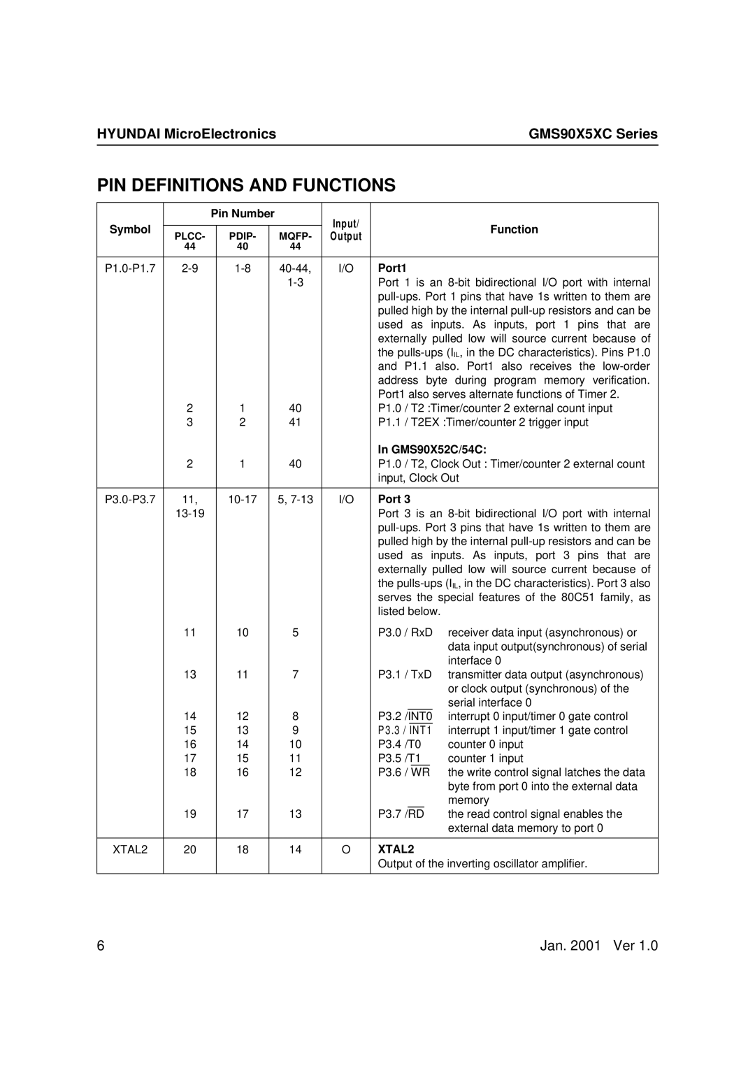
PIN DEFINITIONS AND FUNCTIONS
|
| Pin Number |
| Input/ |
|
|
|
|
|
|
| ||
Symbol |
|
|
|
|
|
|
|
|
|
|
| Function | |
PLCC- |
| PDIP- |
| MQFP- | Output |
|
|
|
|
|
| ||
|
|
|
|
|
|
|
|
|
| ||||
| 44 |
| 40 |
| 44 |
|
|
|
|
|
|
|
|
|
|
|
|
|
|
|
|
| |||||
|
| I/O | Port1 |
| |||||||||
|
|
|
|
|
| Port 1 is an | |||||||
|
|
|
|
|
|
| |||||||
|
|
|
|
|
|
| pulled high by the internal | ||||||
|
|
|
|
|
|
| used as inputs. As inputs, port 1 pins that are | ||||||
|
|
|
|
|
|
| externally pulled low will source current because of | ||||||
|
|
|
|
|
|
| the | ||||||
|
|
|
|
|
|
| and P1.1 also. Port1 also receives the | ||||||
|
|
|
|
|
|
| address byte during program memory verification. | ||||||
|
|
|
|
|
|
| Port1 also serves alternate functions of Timer 2. | ||||||
| 2 |
| 1 |
| 40 |
| P1.0 / T2 :Timer/counter 2 external count input | ||||||
| 3 |
| 2 |
| 41 |
| P1.1 / T2EX :Timer/counter 2 trigger input | ||||||
|
|
|
|
|
|
| In GMS90X52C/54C: | ||||||
| 2 |
| 1 |
| 40 |
| P1.0 / T2, Clock Out : Timer/counter 2 external count | ||||||
|
|
|
|
|
|
| input, Clock Out | ||||||
|
|
|
|
|
|
|
|
| |||||
11, |
|
| 5, | I/O | Port 3 |
| |||||||
|
|
|
|
|
| Port 3 is an | |||||||
|
|
|
|
|
|
| |||||||
|
|
|
|
|
|
| pulled high by the internal | ||||||
|
|
|
|
|
|
| used as inputs. As inputs, port 3 pins that are | ||||||
|
|
|
|
|
|
| externally pulled low will source current because of | ||||||
|
|
|
|
|
|
| the | ||||||
|
|
|
|
|
|
| serves the special features of the 80C51 family, as | ||||||
|
|
|
|
|
|
| listed below. |
| |||||
| 11 |
| 10 |
| 5 |
| P3.0 / RxD | receiver data input (asynchronous) or | |||||
|
|
|
|
|
|
|
|
|
|
|
|
| data input output(synchronous) of serial |
|
|
|
|
|
|
|
|
|
|
|
|
| interface 0 |
| 13 |
| 11 |
| 7 |
| P3.1 / TxD | transmitter data output (asynchronous) | |||||
|
|
|
|
|
|
|
|
|
|
|
|
| or clock output (synchronous) of the |
|
|
|
|
|
|
|
|
|
|
|
|
| serial interface 0 |
| 14 |
| 12 |
| 8 |
| P3.2 / | INT0 |
| interrupt 0 input/timer 0 gate control | |||
| 15 |
| 13 |
| 9 |
| P3.3 / INT1 | interrupt 1 input/timer 1 gate control | |||||
| 16 |
| 14 |
| 10 |
| P3.4 /T0 | counter 0 input | |||||
| 17 |
| 15 |
| 11 |
| P3.5 /T1 | counter 1 input | |||||
| 18 |
| 16 |
| 12 |
| P3.6 / | WR |
| the write control signal latches the data | |||
|
|
|
|
|
|
|
|
|
|
|
|
| byte from port 0 into the external data |
|
|
|
|
|
|
|
|
|
|
|
|
| memory |
| 19 |
| 17 |
| 13 |
| P3.7 | /RD |
| the read control signal enables the | |||
|
|
|
|
|
|
|
|
|
|
|
|
| external data memory to port 0 |
|
|
|
|
|
|
|
|
| |||||
XTAL2 | 20 |
| 18 |
| 14 | O | XTAL2 |
| |||||
|
|
|
|
|
|
| Output of the inverting oscillator amplifier. | ||||||
|
|
|
|
|
|
|
|
|
|
|
|
|
|
6 | Jan. 2001 Ver 1.0 |