Return to Section TOC
Return to Section TOC
Return to Section TOC
Return to Master TOC
Return to Master TOC
Return to Master TOC
|
| TROUBLESHOOTING & REPAIR |
OUTPUT RECTIFIER, STT CHOPPER BOARD AND RECTIFIER MODULE
REMOVAL AND REPLACEMENT (CONTINUED)
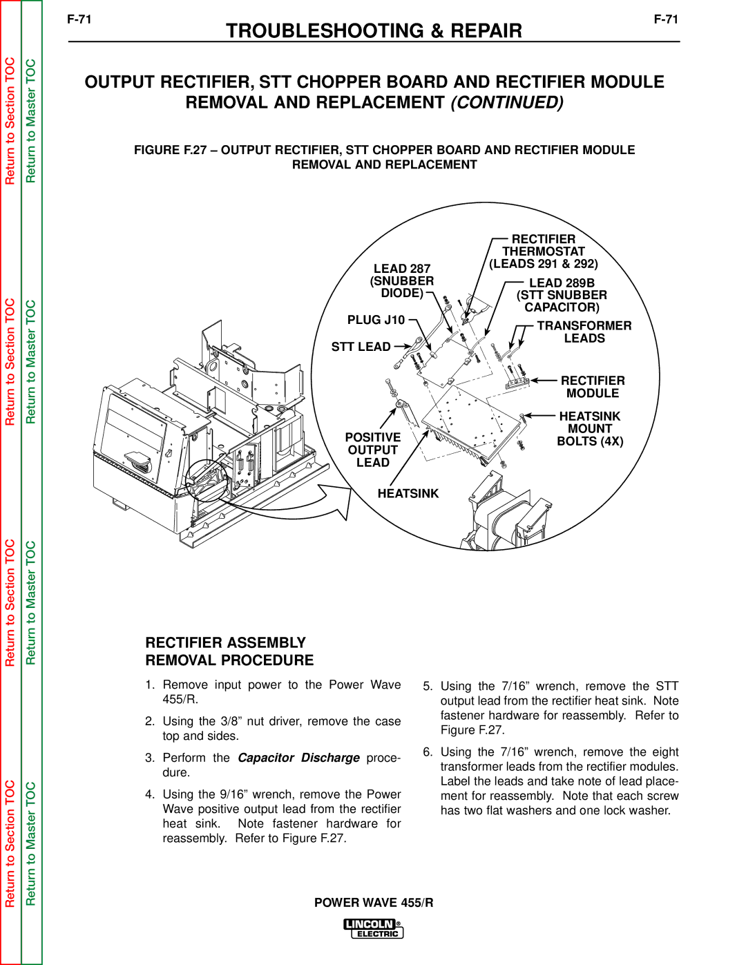
FIGURE F.27 – OUTPUT RECTIFIER, STT CHOPPER BOARD AND RECTIFIER MODULE
REMOVAL AND REPLACEMENT
| RECTIFIER | |
| THERMOSTAT | |
LEAD 287 | (LEADS 291 & 292) | |
| ||
(SNUBBER | LEAD 289B | |
DIODE) | (STT SNUBBER | |
PLUG J10 | CAPACITOR) | |
TRANSFORMER | ||
| ||
STT LEAD | LEADS | |
| ||
| RECTIFIER | |
| MODULE | |
| HEATSINK | |
POSITIVE | MOUNT | |
BOLTS (4X) | ||
OUTPUT | ||
| ||
LEAD |
| |
HEATSINK |
|
RECTIFIER ASSEMBLY
REMOVAL PROCEDURE
Return to Section TOC
Return to Master TOC
1.Remove input power to the Power Wave 455/R.
2.Using the 3/8” nut driver, remove the case top and sides.
3.Perform the Capacitor Discharge proce- dure.
4.Using the 9/16” wrench, remove the Power Wave positive output lead from the rectifier heat sink. Note fastener hardware for reassembly. Refer to Figure F.27.
5.Using the 7/16” wrench, remove the STT output lead from the rectifier heat sink. Note fastener hardware for reassembly. Refer to Figure F.27.
6.Using the 7/16” wrench, remove the eight transformer leads from the rectifier modules. Label the leads and take note of lead place- ment for reassembly. Note that each screw has two flat washers and one lock washer.