SZI 1015
IR Audio Transmission Technology Modulators/Radiators
1 | 2 | 3 | 4 | 5 | 6 | 7 | 8 |
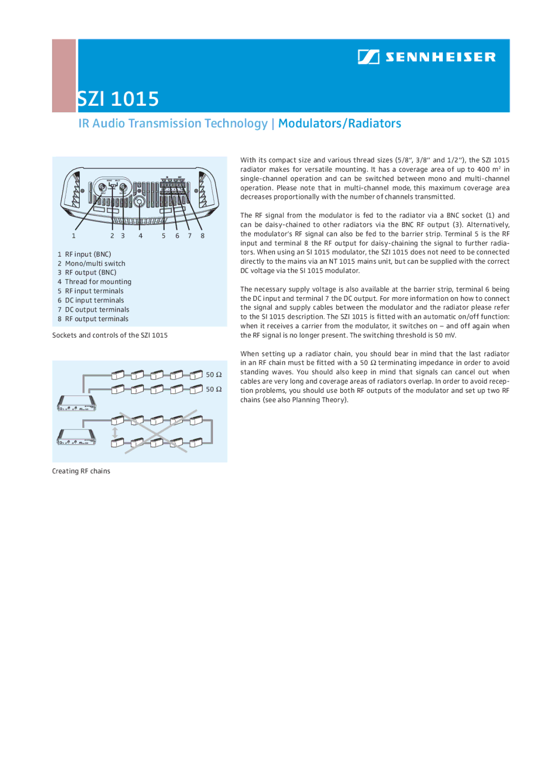
1 RF input (BNC)
2Mono/multi switch
3 RF output (BNC)
4 Thread for mounting
5 RF input terminals
6 DC input terminals
7 DC output terminals
8 RF output terminals
Sockets and controls of the SZI 1015
![]() 50 Ω
50 Ω ![]() 50 Ω
50 Ω
With its compact size and various thread sizes (5/8“, 3/8“ and 1/2“), the SZI 1015 radiator makes for versatile mounting. It has a coverage area of up to 400 m2 in
The RF signal from the modulator is fed to the radiator via a BNC socket (1) and can be
The necessary supply voltage is also available at the barrier strip, terminal 6 being the DC input and terminal 7 the DC output. For more information on how to connect the signal and supply cables between the modulator and the radiator please refer to the SI 1015 description. The SZI 1015 is fitted with an automatic on/off function: when it receives a carrier from the modulator, it switches on – and off again when the RF signal is no longer present. The switching threshold is 50 mV.
When setting up a radiator chain, you should bear in mind that the last radiator in an RF chain must be fitted with a 50 Ω terminating impedance in order to avoid standing waves. You should also keep in mind that signals can cancel out when cables are very long and coverage areas of radiators overlap. In order to avoid recep- tion problems, you should use both RF outputs of the modulator and set up two RF chains (see also Planning Theory).
Creating RF chains