3 1
Setting Up
Your Snow
Thrower
NOTE: References to right or left side of the snow thrower are deter- mined from behind the unit in the operating position.
NOTE: This Operator’s Manual covers several models, handle panels, lights and chute cranks are some features that may vary by model.
Not all features refer- enced in this manual are applicable to all snow thrower models.
NOTE: Two replace- ment auger shear pins are included with this manual (or stowed
in the plastic handle panel). Refer to Augers in the Maintainance Section for more information regarding shear pin replacement.
| IMPORTANT: The snow thrower is shipped with oil | ||
| and WITHOUT GASOLINE. After assembly, refer to | ||
| separate engine manual for proper fuel and engine oil | ||
| recommendations. | ||
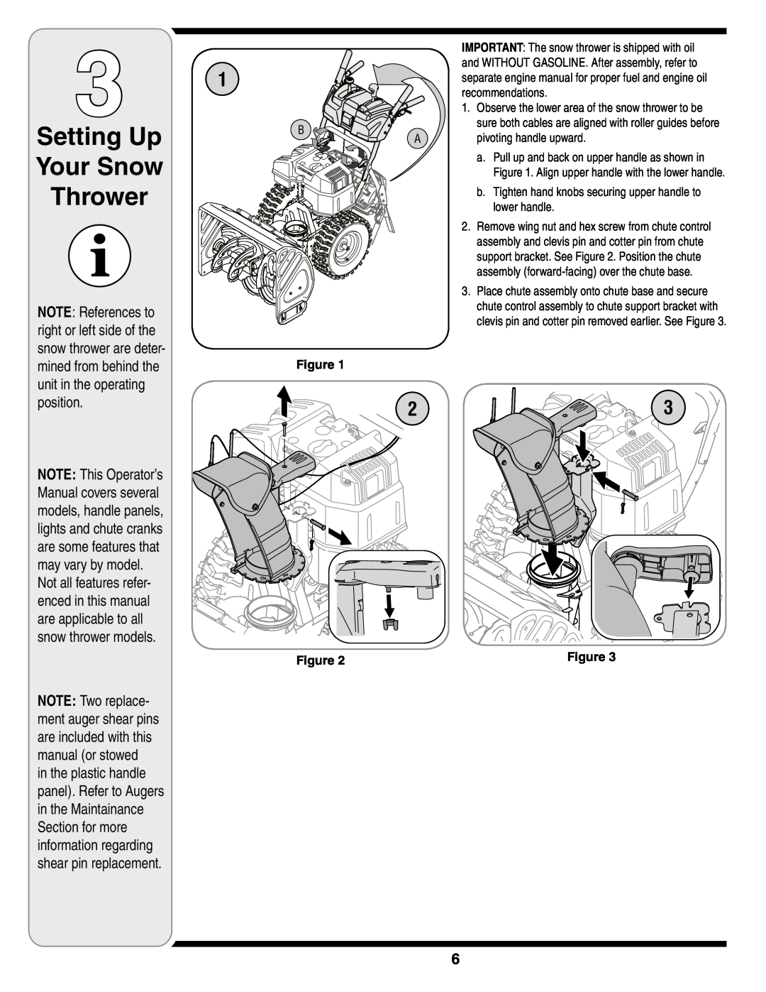
| 1. | Observe the lower area of the snow thrower to be | |
� |
| sure both cables are aligned with roller guides before | |
� | pivoting handle upward. | ||
| |||
|
| a. Pull up and back on upper handle as shown in | |
|
| Figure 1. Align upper handle with the lower handle. | |
|
| b. Tighten hand knobs securing upper handle to | |
|
| lower handle. | |
| 2. | Remove wing nut and hex screw from chute control | |
|
| assembly and clevis pin and cotter pin from chute | |
|
| support bracket. See Figure 2. Position the chute | |
|
| assembly | |
| 3. | Place chute assembly onto chute base and secure | |
|
| chute control assembly to chute support bracket with | |
|
| clevis pin and cotter pin removed earlier. See Figure 3. | |
Figure 1 |
|
| |
| 2 | 3 | |
Figure 2 | Figure 3 |
|
6
