M1102/M1103
Identification
INTRODUCTION
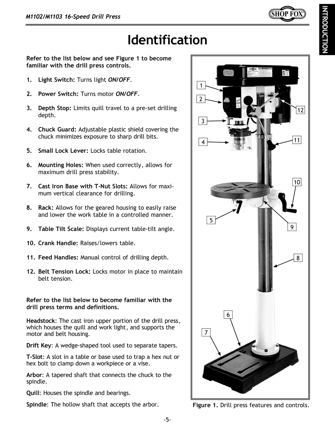
Refer to the list below and see Figure 1 to become familiar with the drill press controls.
1. | Light Switch: Turns light ON/OFF. |
2. | Power Switch: Turns motor ON/OFF. |
3. | Depth Stop: Limits quill travel to a |
| depth. |
4. | Chuck Guard: Adjustable plastic shield covering the |
| chuck minimizes exposure to sharp drill bits. |
5. | Small Lock Lever: Locks table rotation. |
6. | Mounting Holes: When used correctly, allows for |
| maximum drill press stability. |
1![]()
2![]()
![]() 12
12
3
4 | 11 |
|
7. | Cast Iron Base with |
| mum vertical clearance for drilling. |
8. | Rack: Allows for the geared housing to easily raise |
| and lower the work table in a controlled manner. |
9. | Table Tilt Scale: Displays current |
10. | Crank Handle: Raises/lowers table. |
11. | Feed Handles: Manual control of drilling depth. |
12. | Belt Tension Lock: Locks motor in place to maintain |
| belt tension. |
Refer to the list below to become familiar with the drill press terms and definitions.
Headstock: The cast iron upper portion of the drill press, which houses the quill and work light, and supports the motor and belt housing.
Drift Key: A
Arbor: A tapered shaft that connects the chuck to the spindle.
Quill: Houses the spindle and bearings.
5![]()
6
7
10
9
8
Spindle: The hollow shaft that accepts the arbor.
