M381 301603 OpM (Supplemental) NFPA Hood
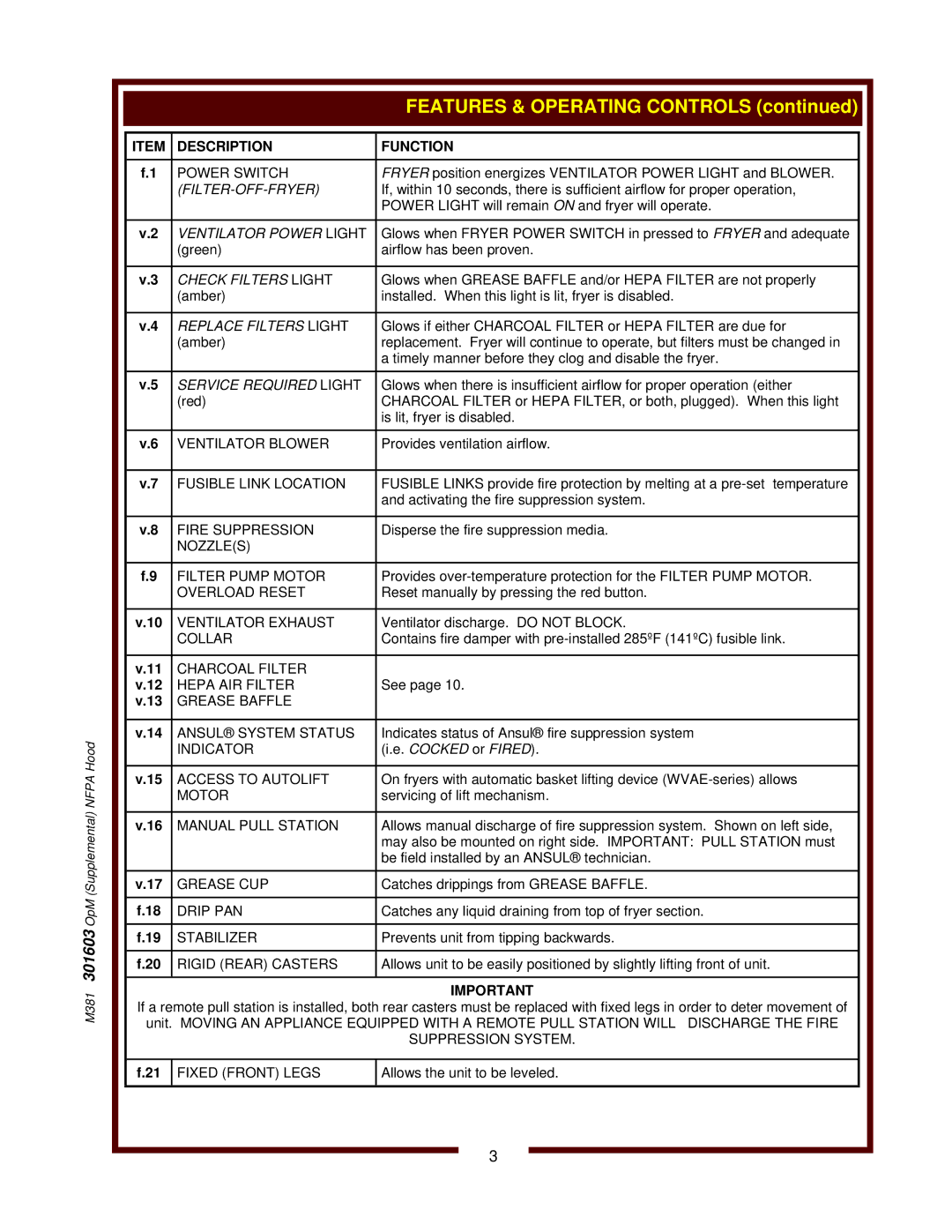
ITEM | DESCRIPTION | FUNCTION |
|
|
|
f.1 | POWER SWITCH | FRYER position energizes VENTILATOR POWER LIGHT and BLOWER. |
|
| If, within 10 seconds, there is sufficient airflow for proper operation, |
|
| POWER LIGHT will remain ON and fryer will operate. |
|
|
|
v.2 | VENTILATOR POWER LIGHT | Glows when FRYER POWER SWITCH in pressed to FRYER and adequate |
| (green) | airflow has been proven. |
|
|
|
v.3 | CHECK FILTERS LIGHT | Glows when GREASE BAFFLE and/or HEPA FILTER are not properly |
| (amber) | installed. When this light is lit, fryer is disabled. |
|
|
|
v.4 | REPLACE FILTERS LIGHT | Glows if either CHARCOAL FILTER or HEPA FILTER are due for |
| (amber) | replacement. Fryer will continue to operate, but filters must be changed in |
|
| a timely manner before they clog and disable the fryer. |
|
|
|
v.5 | SERVICE REQUIRED LIGHT | Glows when there is insufficient airflow for proper operation (either |
| (red) | CHARCOAL FILTER or HEPA FILTER, or both, plugged). When this light |
|
| is lit, fryer is disabled. |
|
|
|
v.6 | VENTILATOR BLOWER | Provides ventilation airflow. |
|
|
|
v.7 | FUSIBLE LINK LOCATION | FUSIBLE LINKS provide fire protection by melting at a |
|
| and activating the fire suppression system. |
|
|
|
v.8 | FIRE SUPPRESSION | Disperse the fire suppression media. |
| NOZZLE(S) |
|
|
|
|
f.9 | FILTER PUMP MOTOR | Provides |
| OVERLOAD RESET | Reset manually by pressing the red button. |
|
|
|
v.10 | VENTILATOR EXHAUST | Ventilator discharge. DO NOT BLOCK. |
| COLLAR | Contains fire damper with |
|
|
|
v.11 | CHARCOAL FILTER |
|
v.12 | HEPA AIR FILTER | See page 10. |
v.13 | GREASE BAFFLE |
|
|
|
|
v.14 | ANSUL® SYSTEM STATUS | Indicates status of Ansul® fire suppression system |
| INDICATOR | (i.e. COCKED or FIRED). |
|
|
|
v.15 | ACCESS TO AUTOLIFT | On fryers with automatic basket lifting device |
| MOTOR | servicing of lift mechanism. |
|
|
|
v.16 | MANUAL PULL STATION | Allows manual discharge of fire suppression system. Shown on left side, |
|
| may also be mounted on right side. IMPORTANT: PULL STATION must |
|
| be field installed by an ANSUL® technician. |
|
|
|
v.17 | GREASE CUP | Catches drippings from GREASE BAFFLE. |
|
|
|
f.18 | DRIP PAN | Catches any liquid draining from top of fryer section. |
|
|
|
f.19 | STABILIZER | Prevents unit from tipping backwards. |
|
|
|
f.20 | RIGID (REAR) CASTERS | Allows unit to be easily positioned by slightly lifting front of unit. |
|
|
|
IMPORTANT
If a remote pull station is installed, both rear casters must be replaced with fixed legs in order to deter movement of unit. MOVING AN APPLIANCE EQUIPPED WITH A REMOTE PULL STATION WILL DISCHARGE THE FIRE SUPPRESSION SYSTEM.
f.21 | FIXED (FRONT) LEGS | Allows the unit to be leveled. |
|
|
|
3
