701379-UIM-C-0712

C

D(Min)

Field

Fabricated

Ductwork

Upflow

Coil

Upflow

Furnace

Flexible Duct Collar

Do not drill or Screw this flange

DOWNFLOW DUCT CONNECTORS

All downflow installations must use a suitable duct connector approved by the furnace manufacturer for use with this furnace. The duct connec- tors are designed to be connected to the rectangular duct under the floor and sealed. Refer to the instructions supplied with the duct con- nector for proper installation. Refer to the separate accessory parts list at the end of these instructions for the approved accessory duct con- nectors.

FURNACE

WARM AIR PLENUM

WITH 1” FLANGES

Primary

Secondary

Alternate

Drain

Drain Location

Drain


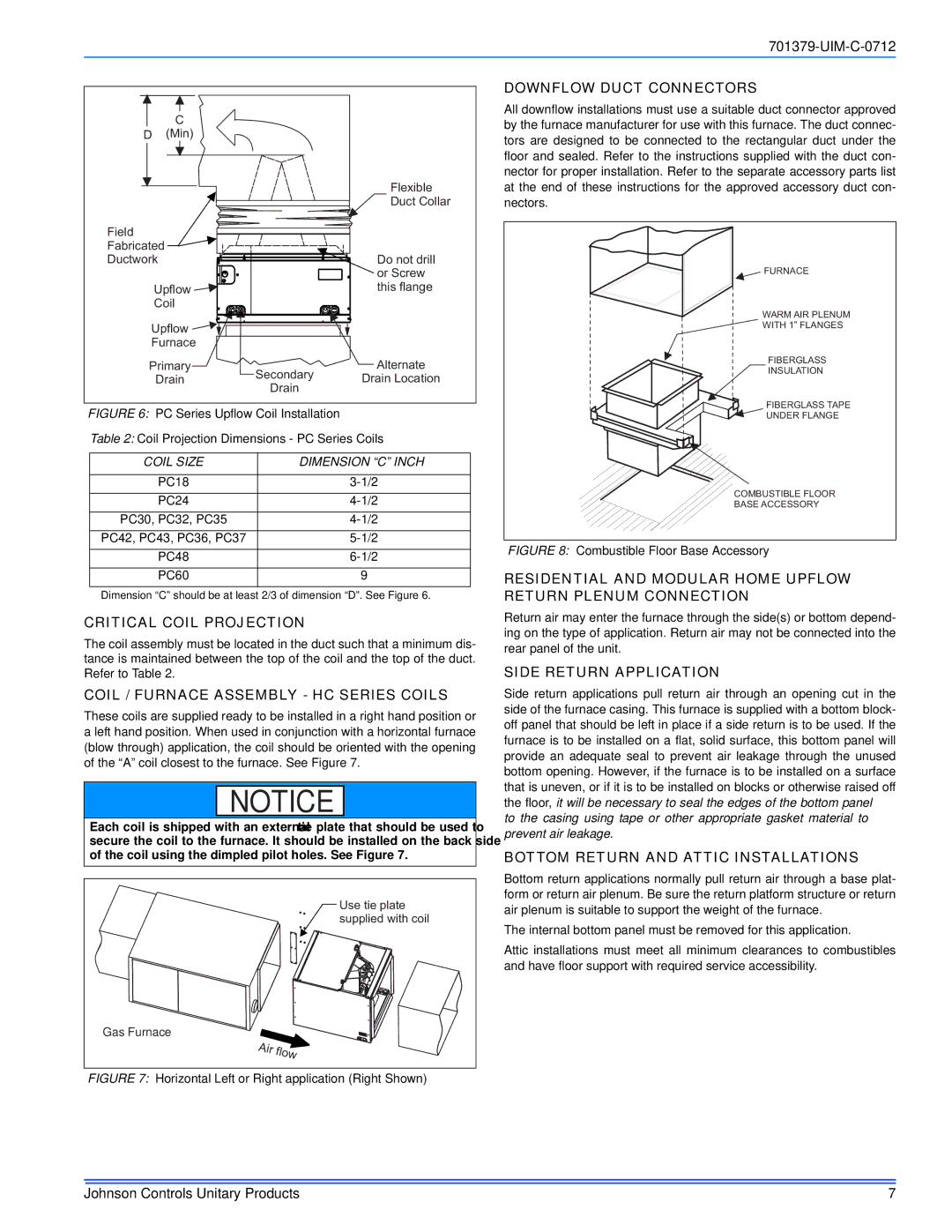
FIGURE 6: PC Series Upflow Coil Installation

Table 2: Coil Projection Dimensions - PC Series Coils

COIL SIZE

DIMENSION “C” INCH


PC18

3-1/2


PC24

4-1/2


PC30, PC32, PC35

4-1/2


PC42, PC43, PC36, PC37

5-1/2


PC48

6-1/2


PC60

9


Dimension “C” should be at least 2/3 of dimension “D”. See Figure 6.

CRITICAL COIL PROJECTION

The coil assembly must be located in the duct such that a minimum dis- tance is maintained between the top of the coil and the top of the duct. Refer to Table 2.

COIL / FURNACE ASSEMBLY - HC SERIES COILS

These coils are supplied ready to be installed in a right hand position or a left hand position. When used in conjunction with a horizontal furnace (blow through) application, the coil should be oriented with the opening of the “A” coil closest to the furnace. See Figure 7.

NOTICE

Each coil is shipped with an external tie plate that should be used to secure the coil to the furnace. It should be installed on the back side of the coil using the dimpled pilot holes. See Figure 7.

Use tie plate

supplied with coil

Gas Furnace

FIGURE 7: Horizontal Left or Right application (Right Shown)

FIBERGLASS

INSULATION

FIBERGLASS TAPE

UNDER FLANGE

COMBUSTIBLE FLOOR

BASE ACCESSORY

FIGURE 8: Combustible Floor Base Accessory

RESIDENTIAL AND MODULAR HOME UPFLOW RETURN PLENUM CONNECTION

Return air may enter the furnace through the side(s) or bottom depend- ing on the type of application. Return air may not be connected into the rear panel of the unit.

SIDE RETURN APPLICATION

Side return applications pull return air through an opening cut in the side of the furnace casing. This furnace is supplied with a bottom block- off panel that should be left in place if a side return is to be used. If the furnace is to be installed on a flat, solid surface, this bottom panel will provide an adequate seal to prevent air leakage through the unused bottom opening. However, if the furnace is to be installed on a surface that is uneven, or if it is to be installed on blocks or otherwise raised off the floor, it will be necessary to seal the edges of the bottom panel to the casing using tape or other appropriate gasket material to prevent air leakage.

BOTTOM RETURN AND ATTIC INSTALLATIONS

Bottom return applications normally pull return air through a base plat- form or return air plenum. Be sure the return platform structure or return air plenum is suitable to support the weight of the furnace.

The internal bottom panel must be removed for this application.

Attic installations must meet all minimum clearances to combustibles and have floor support with required service accessibility.

Johnson Controls Unitary Products

7

Page 7
Image 7
Johnson Controls TM9V*MP Downflow Duct Connectors, Critical Coil Projection, Coil / Furnace Assembly HC Series Coils

TM9V*MP specifications

Johnson Controls has long been a leader in providing innovative comfort solutions, and their TM9V*MP series of variable speed air handlers is a testament to their commitment to efficiency and performance. These products are designed to optimize heating and cooling in both residential and commercial applications, ensuring superior indoor air quality and comfort year-round.

One of the standout features of the TM9V*MP series is its variable speed technology. Unlike traditional single-speed systems, the TM9V*MP adjusts its airflow according to real-time heating and cooling demands. This not only enhances comfort by maintaining consistent temperatures but also significantly reduces energy consumption. The variable speed motor operates quietly and efficiently, making it ideal for both living environments and workplaces.

In terms of design, the TM9V*MP is engineered for ease of installation and maintenance. It comes in a compact size that allows for flexible positioning within existing ductwork, making retrofits simpler for contractors. Additionally, the modular design allows for easy access to internal components, which facilitates hassle-free servicing and maintenance.

The unit also features a robust filtration system that works in tandem with a range of air quality technologies. This includes optional media filters that capture allergens and particulates, ensuring that the air quality within a space is not only comfortable but also healthy. The integration of advanced technologies, such as integrated Wi-Fi capabilities, provides users with the ability to monitor and adjust settings remotely via smartphones or tablets.

Moreover, the TM9V*MP series is compatible with a wide range of communication protocols, enabling seamless connectivity with smart home systems. This means that users can create customized comfort profiles and take advantage of energy-saving features automatically.

Durability is another key characteristic of the TM9V*MP series. Built with high-quality materials and subjected to rigorous testing, these air handlers are designed to endure even the most demanding conditions while providing reliable performance over time.

In summary, Johnson Controls' TM9V*MP series offers an array of features that cater to modern comfort demands. With its variable speed technology, user-friendly design, air quality enhancements, and strong connectivity options, it stands out as a prime choice for both residential and commercial HVAC applications, setting a high standard for efficiency and indoor comfort.