Chapter 2 Installation | MBE Family Installation and Operation Manual |
|
|
9.To enable direct connection between MBE and a UTP interface in any workstation, set the STATION/HUB Switch to STATION (see Figure
10.Replace the MBE cover.
11.Close by tightening the cover screw.
12.Proceed with the line, LAN and power connections as described below.
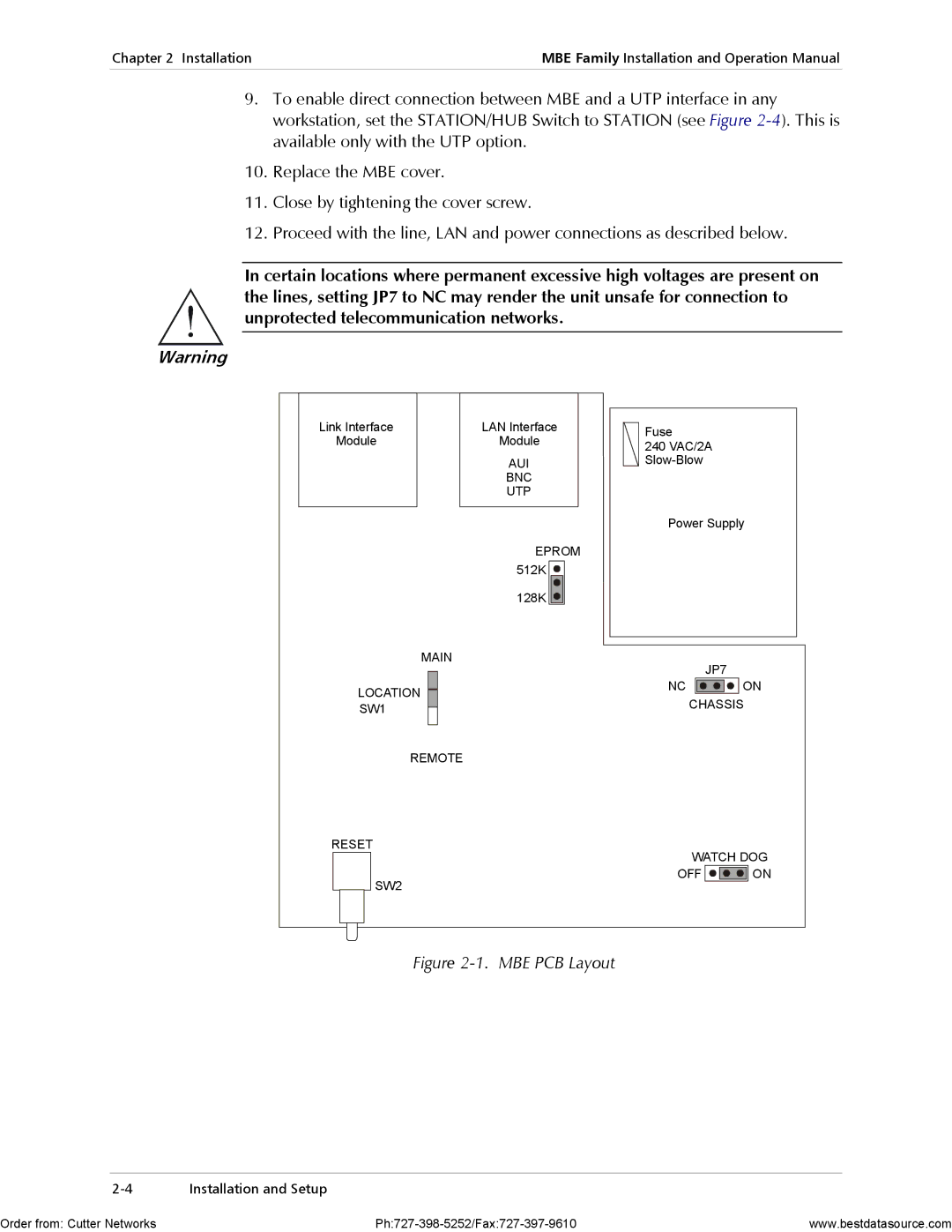
In certain locations where permanent excessive high voltages are present on the lines, setting JP7 to NC may render the unit unsafe for connection to unprotected telecommunication networks.
Warning
Link Interface | LAN Interface |
Module | Module |
AUI
BNC
UTP
EPROM
512K |
128K |
MAIN
LOCATION
SW1
REMOTE
RESET
SW2
Fuse
240VAC/2A
Power Supply
JP7
NC ![]()
![]()
![]()
![]() ON
ON
CHASSIS
WATCH DOG
OFF ![]()
![]()
![]()
![]() ON
ON
Figure 2-1. MBE PCB Layout
Installation and Setup |
Order from: Cutter Networks | www.bestdatasource.com |