INTERRUPT STRUCTURE
The SMC91C95 merges two main interrupt sources into a single interrupt line. One source is the Ethernet interrupt and the other is the modem interrupt. The Ethernet interrupt is conceptually equivalent to the SMC91C92 interrupt line; it is the OR function of all enabled interrupts within the Ethernet core. The modem interrupt is an input pin (MINT). The enabling, reporting and clearing of these two sources is controlled by the ECOR, ECSR, MCOR and MCSR registers. The interrupt
structure is similar for ISA and PCMCIA modes with the following exceptions:
a)PCMCIA uses a single interrupt pin (nIREQ) while ISA can use any of four
b)PCMCIA defaults to Ethernet interrupts disabled (Enable IREQ=0 in ECOR), while ISA defaults to Ethernet interrupts enabled.
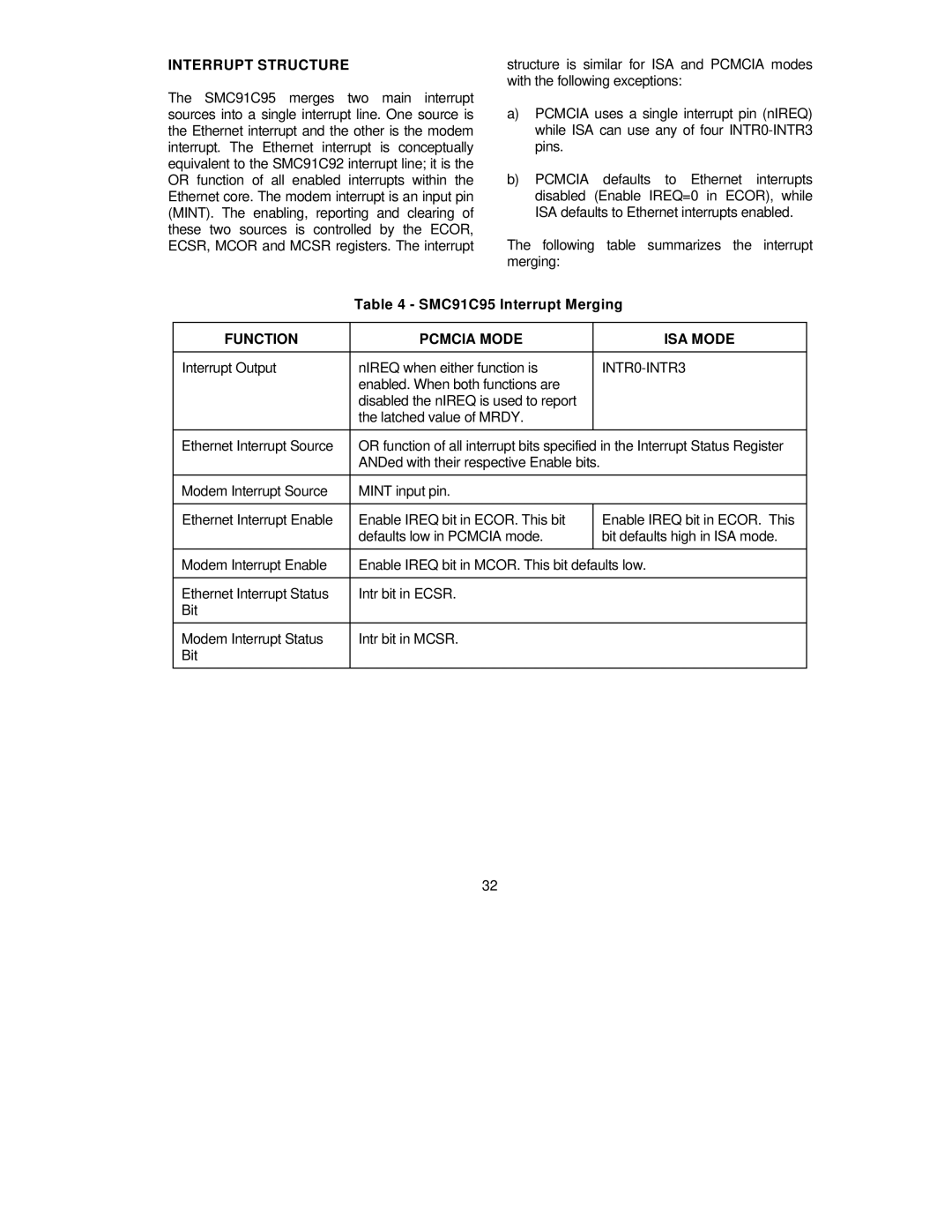
The following table summarizes the interrupt merging:
Table 4 - SMC91C95 Interrupt Merging
FUNCTION | PCMCIA MODE |
| ISA MODE |
|
|
|
|
Interrupt Output | nIREQ when either function is |
|
|
| enabled. When both functions are |
|
|
| disabled the nIREQ is used to report |
|
|
| the latched value of MRDY. |
|
|
|
|
| |
Ethernet Interrupt Source | OR function of all interrupt bits specified in the Interrupt Status Register | ||
| ANDed with their respective Enable bits. |
| |
|
|
| |
Modem Interrupt Source | MINT input pin. |
| |
|
|
| |
Ethernet Interrupt Enable | Enable IREQ bit in ECOR. This bit |
| Enable IREQ bit in ECOR. This |
| defaults low in PCMCIA mode. |
| bit defaults high in ISA mode. |
|
|
| |
Modem Interrupt Enable | Enable IREQ bit in MCOR. This bit defaults low. | ||
|
|
| |
Ethernet Interrupt Status | Intr bit in ECSR. |
| |
Bit |
|
|
|
|
|
| |
Modem Interrupt Status | Intr bit in MCSR. |
| |
Bit |
|
|
|
|
|
|
|
32