Black Box PI125A-R2, PI126A manual 3 4 5 6 7

Page 14

CHAPTER 3: Configuration and Installation

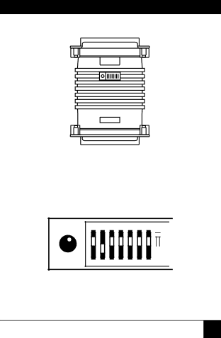
Figure 3-1. The location of the configuration switches.

1 2 3 4 5 6 7 8

OFF

DHS-8

Figure 3-2. The miniature configuration switch package.

11

Image 14
Contents Copyright 2001. Black Box Corporation. All rights reserved Customer Support Information Page Trademarks Used In This Manual SERIAL↔PARALLEL Converters NOM Statement SERIAL↔PARALLEL Converters Contents Specifications Size Introduction DescriptionFeatures Configuration and Installation Configuration Switches3 4 5 6 7 SERIAL↔PARALLEL Converters Configuration and Installation Installation Typical installationReading the LED Troubleshooting