Acer M3900 manual Standard Cmos Features, Parameter Description Option

Page 24

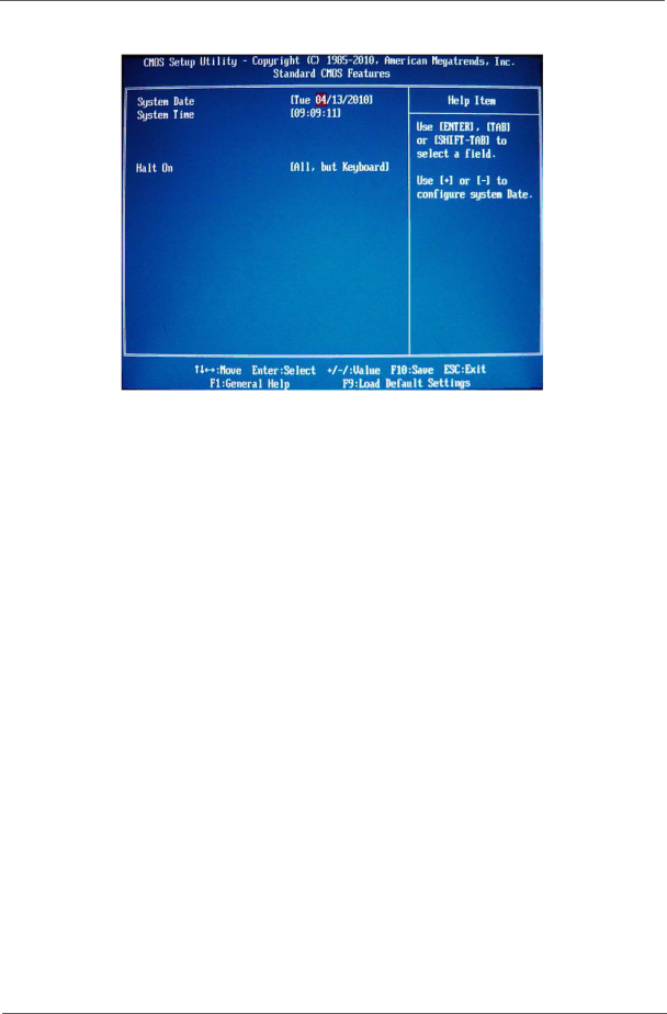
Standard CMOS Features

Parameter

Description

Option


System Date

Set the date following the weekday-month-day-year format.


System Time

Set the system time following the hour-minute-second format.


Halt On

Determines whether the system will stop for an error during the POST.

All, But Keyboard


No Errors


All Errors


Chapter 2

16

Image 24
Contents Acer Aspire M3900 Service Guide Revision History Copyright Disclaimer Conventions Service Guide Coverage Table of Contents FRU Field Replaceable Unit List Features ChapterOn-Board Graphic solution AudioHard disk Optical diskUSB ports Extension slotTotal I/O ports System Bios Power supplyBlock Diagram System Components Front PanelRear Panel Hardware Specifications and Configurations IOS Hotkey ListMain Board Major Chips Memory Combinations System MemoryAudio Interface Power Management Sata InterfaceUSB Port Environmental RequirementsPower Management FunctionACPI support function Device Standby ModeGlobal Standby Mode Suspend ModeCmos Setup Utility System Utilities Entering Cmos setup Navigating Through the Setup UtilitySetup Utility Menus Parameter DescriptionProduct Information Standard Cmos Features Parameter Description OptionAdvanced Bios Feature EnabledAdvanced Chipset Features Integrated Peripherals Power Management Setup PC Health Status Frequency/Voltage Control Bios Security Features Setting a supervisor passwordLoad Default Settings Save & Exit Setup Exit Without Saving System Disassembly Disassembly RequirementsPre-disassembly Procedure Removing the Side Panel Removing the Heat Sink Fan Assembly Page Removing the Processor Removing the VGA Card Removing the TV Card Removing the Mode Card Removing the Memory Modules Removing the Hard Disk Drive Chapter Removing the USB Board of Rear Panel Chapter Removing the Front Bezel Pull the bezel away from the chassis Removing the Optical Drive Chapter Removing the Removable HDD Chapter Page Removing the Power Supply Lift the power supply module out of the chassis Chapter Removing the Card Reader Pull the card reader out of chassis Chapter Removing the Mainboard Page System Troubleshooting Power System Check System External InspectionSystem Internal Inspection Beep Codes Viewing Bios checkpoints Bootblock Initialization Code CheckpointsCheckpoints System is waking from Acpi S3 state Bootblock Recovery Code Checkpoints Checkpoint DescriptionBios Recovery Jumper and Connector Information PlacementLabel Description Jumper Setting Setting JumperInternal header pin definition Front USB Header USBVCC1 Connector pin definition Connector Name Function DefinitionSATA1TXP SATA1TXN ATX12V Conn FRU Field Replaceable Unit List Aspire M3900 Exploded DiagramAM350-ASSY Aspire M3900 Exploded DiagramAM351-ASSY Aspire M3900 FRU List Components Model Name or Key Spec Acer P/NCPU VGA NV GT330 2GB DDR2 DVI+HDMI+VGA ATX Samsung Geforce 310 512MB DDR2 Samsung 64BITS VGA DVI Hdmi Components Model Name or Key Spec Acer P/N