ViewSonic VSXXXXX service manual Reader’s Response, Name Company Add Tel Mail Title Fax

Page 67

* Reader’s Response*

Dear Readers:

Thank you in advance for your feedback on our Service Manual, which allows continuous improvement of our products. We would appreciate your completion of the Assessment Matrix below, for return to ViewSonic Corporation.

Assessment

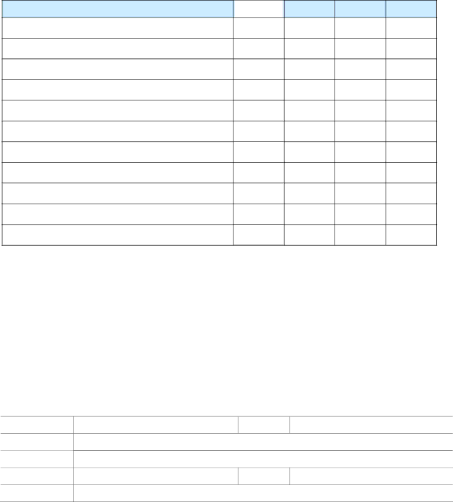
A.What do you think about the content of this Service Manual?

Unit

1.Precautions and Safety Notices

2.Specification

3.Front Panel Function Control Description

4.Circuit Description

5.Adjustment Procedure

6.Troubleshooting Flow Chart

7.Block Diagrams

8.Schematic Diagrams

9.PCB Layout Diagrams

10.Exploded Diagram and Exploded Parts List

11.Recommended Spare Parts List

Excellent

Good

Fair

Bad

B. Are you satisfied with this Service Manual?


Item

Excellent

Good

Fair

Bad

1.

Service Manual Content


2.

Service Manual Layout


3.

The form and listing


C. Do you have any other opinions or suggestions regarding this service manual?

Reader’s basic dada:

Name:

Company:

Add:

Tel:

E-mail:

Title:

Fax:

After completing this form, please return it to ViewSonic Quality Assurance in the USA at facsimile 1-909-839-7943. You may also e-mail any suggestions to the Director, Quality Systems & Processes (marc.maupin@viewsonic.com)

67

Image 67
Contents VG2427wmSM Rev a Mar ViewSonic VG2427wmTdrmnddbwbvspc TdrmnddkwbvspcTdrmnddywbvspc TdrmnddcwbvspcTable of Contents Service Notes Precautions and Safety NoticesSafety Precautions Product Safety NoticeCorrect Methods Incorrect Methods Handing and Placing MethodsPage Specification Front Panel Function Control Description Following tips may help you optimize your display Do the following to adjust the display settingMain Menu Controls Audio AdjustControl Explanation Page Page Main Board Circuit DescriptionPin Assignment Page Page Page Page Name Pin # Pin DescriptionsFunction Typical Application Power BoardComp GND OUT VCC Block Diagram PinIC801 TA9687GN Pin Diagram Functional Block DiagramPin Description Pin No Names Enter into the factory mode Adjustment ProcedureWhite balance, Luminance adjustment Enter into Burn/in modeISP Board Firmware Upgrade ProcedureEquipment needed PC LPT Hardware Connect status Update the NOVATEK’S firmwarePage Page Install software DDC Key in ProcedureFor analog Page Troubleshooting Flow Chart Block Diagram Mosfet ON/OFFDIM 0R05 1/10W 5% Schematic DiagramsFB402 TO252 0402 Power Board Power XFMR7 IC with Heat-sink90G6295-3 TPV Model Key BoardPCB Name Upstream USB BoardPCB Layout Diagrams Page Power Board Page Key Board USB Board Page 10.1 EPL Exploded Diagram and Exploded Parts ListDescription Part Number Qty 10.2 PPL Location Part Number Description Remark Recommended Spare Parts ListWafer 30P 2.0MM DIP Dual ROW Cbpc LabelWafer CONN.6P 1.0 DIPPage RST Chipr RST Chip MAXChip 22PF 50V NPO Chip Bead FCM2012VF-301T07 Bullwill Chip 5PF 50V NPOBead 300Ω Chip BeadTRA LMBT3904LT1G 200MA/40V SOT-23 LRC Dome Switch 5PCSPIN PWPC9D41MQWU Power Board UDZSNP5.6B RohmChoke by LI TA IC PC123Y22FZ0FRST Ntcr 8OHM £«£20£¥ 4A Xianzheng CAP CER 56PF J 3KVScrew HS2 Screw HS1Heat Sink Diode SP1060 ITO-220 SecosRST Chipr 1K RST Chipr 3.6KRST Chipr 6.2KOHM +-5% 1/10W Yageo 1ST ChiprX7R RST Chipr 820KOHM +-5% 1/4W FenghuaNPO BAV70 SOT23 by PAN JIT Power Board PCBJumper Wire Chip Bead HCB3216KF-800T30 BullwillPallet Label ConnectorVSC 23.6 Hinge Assy HT POT LabelUSB Board PCB Diode ESD EGA 10603V05A1-B InpaqRST Chip MAX 0R05 1/4W Diversity of Tdrmnddbwbvspc compared with Tdrmnddkwbvspc Different Parts ListDiversity of Tdrmnddcwbvspc compared with Tdrmnddkwbvspc Location Part Number DescriptionName Company Add Tel Mail Title Fax Reader’s Response