Contents
YFM400FAR
YFM400FAR
Important Information
Manual Organization
Exploded Diagrams
GEN Spec Info CHK ENG ADJ
Table of Contents
Contents Chapter General Information
Introduction
Seat and Side Panels
Fuel Tank
Chapter Engine
Page
Chapter Cooling System
Rear AXLE/FINAL Drive Gear and Drive Shaft
Troubleshooting
Chapter Chassis
Front Arms and Front Shock Absorbers
Chapter Electrical
Starting FAILURE/HARD Starting
Faulty Drive Train
Faulty Gear Shifting
Faulty Clutch Performance
Malfunction
Faulty Brake
Overheating
Poor Braking Effect
Model Label
Vehicle Identification Number
Preparation for Removal Procedures
Replacement Parts
GASKETS, OIL Seals and O-RINGS
Lock WASHERS/PLATES and Cotter Pins
Bearings and OIL Seals
Circlips
Checking of Connections
Tool No Tool name/How to use Illustration
Crankshaft installer set
Sheave fixed block
Compression gauge
Clutch holding tool
General Specifications
Mikuni
DR8EA/NGK
Maxxis
YTX14AH
Engine
Seat Width Margin Thickness Head Diameter Face Width
41.27 mm
Spec
Spec
Spec
Pressure feed Splashed scavenge Camshaft Crank Pin
Standard Limit Cylinder head tightening sequence
Tightening torques
Neutral switch M10 Reverse switch Stator assembly
Chassis
DOT
Tightening torques
Spec
Electrical
MS5F-561/JIDECO
4BA/DENSO
5ND/NIPPON Thermostat
Conversion Table
Metric Multiplier Imperial
Lubrication Points and Lubricant Types
Coolant Flow Diagrams
Radiator Thermostat To coolant reservoir
OIL Flow Diagrams
Oil filter
Oil pump Oil strainer
Cable Routing
Spec
Spec
Spec
Spec
Spec
Spec
Spec
Spec
Spec
Introduction
CHK ADJ
Removing the seat and side panels
Seat and Side Panels
Front CARRIER, Front Bumper and Front Fender
Removing the front carrier, front
Bumper and front fender
CHK ADJ
First disconnect the negative lead
Rear Carrier and Rear Fender
Removing the rear carrier and rear
Fender
CHK ADJ
Fuel Tank
Removing the fuel tank
Bumper and Front Fender
Removing the footrest boards
Adjusting the Valve Clearance
Adjusting the Valve Clearance
Adjustment steps
Tappet adjusting tool YM-08035
Locknut 20 Nm 2.0 m kg, 14 ft lb
Engine idling speed 1,450 ~ 1,550 r/min
Adjusting the Idling Speed
Adjusting the Throttle Lever Free Play
Turning Idling speed becomes Higher Turning out Lower
Throttle lever free play ~ 5 mm 0.12 ~ 0.20
Adjustment steps First step
Adjusting the Speed Limiter
Second step
Speed limiter length 12 mm 0.47
Adjusting the Starter Cable
Speed limiter length adjustment steps
Starter plunger stroke distance 15 mm 0.59
Checking the Spark Plug
Standard spark plug DR8EA/NGK
Spark plug gap ~ 0.7 mm 0.024 ~ 0.028
Loctite
Checking the Ignition Timing
Engine speed 1,450 ~ 1,550 r/min
Recoil starter bolt 10 Nm 1.0 m kg, 7.2 ft Ib
Compression gauge YU-33223 Adapter YU-33223-3
Measuring the Compression Pressure
Measuring the Compression Pressure
Recommended oil Follow the left chart
Checking the Engine OIL Level
Do not allow foreign material to enter the crankcase
Replacement steps
Changing the Engine OIL
Oil filter wrench YU-38411
Oil filter cartridge 17 Nm 1.7 m kg, 12 ft lb
Cautio N
Oil gallery bolt Nm 0.7 m kg, 5.1 ft lb
Cleaning the AIR Filter
Cleaning the AIR Filter
Cleaning steps
Checking the Coolant Level
Changing the Coolant
10 Nm 1.0 m kg, 7.2 ft lb
CHK ADJ
Checking the Coolant Temperature
Checking the V-BELT
Belt width 30.7 mm 1.21 in Limit 27.6 mm 1.09
Replacing steps
Cleaning the Spark Arrester
Adjusting the Rear Brake
Rear brake pedal free play 20 ~ 30 mm 0.80 ~ 1.18
Rear brake pedal free play 20 ~ 30 mm 0.8 ~ 1.2
Gap a ~ 1 mm 0.00 ~ 0.04
Checking the Front Brake Fluid Level
Recommended brake fluid
DOT
Checking the Front Brake Pads
Brake pad wear limit a 1 mm 0.04
Checking the Rear Brake Shoes
Checking the Brake Hoses
Bleeding the Hydraulic Brake System
Air bleeding steps
Bleed screw Nm 0.6 m kg, 4.3 ft lb
Adjustment steps Control cable
Adjusting the Select Lever Control Cable and Shift ROD
Select lever shift rod
Adjusting the Rear Brake Light Switch
Direction a Brake light comes on Sooner Direction b Later
Checking the Final Gear OIL Level
Recommended oil SAE 80 API GL-4 Hypoid gear oil
Changing the Final Gear OIL
Changing the Differential Gear OIL
Checking the Constant Velocity Joint Dust Boots
Checking the Steering System
Adjusting the TOE-IN
Locknut rod end 40 Nm 4.0 m kg, 29 ft lb
Toe-in = É È
Adjusting the Front Shock Absorbers
Adjusting the Rear Shock Absorber
Checking the Tires
Maximum Loading Limit
Tire Characteristics
Manufacturer Size Type
Maxxis
Cold tire Front Rear
Checking and Lubricating the Cables
Checking the Wheels
Recommended lubricant Lithium soap base grease
Lubricating the LEVERS, PEDAL, ETC
Charging Method
Checking the Battery
Keep Batteries and Electrolyte OUT of Reach of Children
Battery condition checking steps
Open-circuit Charging time
Or higher No charging is Necessary
Example
YES
Charging method using a variable voltage charger
Charging method using a constant voltage charger
Checking the Fuses
Pocket tester YU-03112-C
Description
Quantity
Changing the Headlight Bulb
Adjusting the Headlight Beams
Changing the Headlight Bulb
AIR DUCTS, Muffler and Exhaust Pipe
Removing the air ducts, muffler
Exhaust pipe
ENG
Select Lever Unit and Coolant Reservoir
Removing the select lever unit
Coolant reservoir
Removing the hoses and leads
Hoses and Leads
Tighten Them to full torque
Install all of the bolts/nuts and then
Specifications
Engine Mounting Bolts
ENG
Installing the Engine
Removing the cylinder head
Cylinder Head
Rotor holding tool YU-01235
Removing the Cylinder Head
Checking the Tappet Covers
Checking the Timing Chain Tensioner
Checking the Camshaft Sprocket
ENG
Installing steps
Installing the Cylinder Head
Cap bolt timing chain tensioner 23 Nm 2.3 m kg, 17 ft lb
Installation steps
Tighten Camshaft sprocket bolt
Valves and Valve Springs
Removing the camshaft, rocker
Arms and valves
Camshaft and Rocker Arms
ENG
Slide hammer set YU-01083-A Slide hammer bolt M6 Weight
Removing the Camshaft and Rocker Arms
Removing the Valves and Valve Springs
Valve spring compressor YM-04019
Checking the Camshaft
Checking the Rocker Arms and Camshaft
Check Rocker arms Rocker arm shafts Damage/wear → Replace
Checking the Valves and Valve Springs
Runout limit 01 mm 0.0004
Lapping steps
U T ION
Installed length
Spring tilt limit Inner 1.6 mm 0.06 in Outer
Installing the Valves and Valve Springs
Installing the Camshaft and Rocker Arms
Piston
Removing the cylinder and piston
Checking the Timing Chain Guide
Removing the Piston
Piston pin puller set YU-01304
Do not use a hammer to drive the piston pin out
0016
Measurement steps 1st step
Cylinder bore C 84.500 ~ 84.510 mm 3268 ~ 3.3272
05 mm
Standard Limit Top 03 ~ 0.08 mm 13 mm Ring
3rd step
Checking the Piston Rings
Side clearance
~ 0.7 mm Ring
End gap Standard Limit
~ 0.40 mm 65 mm Ring
2nd ~ 0.60 mm 95 mm Ring
Installing the Piston
Installing the Cylinder
Removing the A.C. magneto
Chapter
Magneto
ENG
Disassembling the recoil starter
Assembling the Recoil
Starter
Checking the A.C. Magneto
Removing the A.C. Magneto
Flywheel puller YM-01404
Disassembling the Recoil Starter
Bolts starter clutch 30 Nm 3.0 m kg, 22 ft lb
Checking the Starter Clutch
Checking the Starter Pulley
Checking the Recoil Starter
Assembling the Recoil Starter
Sealant Quick Gasket ACC-11001-05-01 Yamaha bond No
Installing the A.C. Magneto
Use a rotor holding tool 2 to hold the starter pulley
Sheaves
Removing the primary
Secondary sheaves
Primary and Secondary
For installation, reverse the removal
Sheave
Primary Sliding Sheave
Disassembling the primary sliding
Sheave
Secondary Sheave
Disassembling the secondary
Assembling the Secondary
Removing steps
Removing the Primary Secondary Sheaves
Sheave holder YS-01880-A
Disassembling the Secondary Sheave
Free length 121.4 mm 4.78 Limit 115.33 mm 4.54
Weight outside diameter 30 mm 1.18 Limit 29.5 mm 1.16
Checking the Primary Sheave
Checking the Secondary Sheave
Assembling the Secondary Sheave
Assembling the Primary Sheave
Nut 90 Nm 9.0 m kg, 65 ft lb
Installing the Primary and Secondary Sheaves
Clutch
Removing the clutch
Disassembling the clutch housing
Removing the Clutch
Clutch holding tool YM-91042
Checking the Clutch
Installing the Clutch
Install Dowel pins Gasket New Clutch housing assembly
OIL Pump Drive Gear
Starter MOTOR, Timing Chain and OIL Filter
Removing the starter motor, timing
Chain and oil filter
ENG
Crankcase
Separating the crankcase
Lever
Crankcase Bearings
Removing the crankcase bearings
Pump
Separation steps
Removing the OIL Pump Drive Gear
Removal steps
Separating the Crankcase
Checking the OIL Strainer and OIL Delivery Pipe
Checking the Timing Chain and Guide
Checking the Crankcase
Checking the Bearings
Assembling the Crankcase
Installing the Shift Lever
Tightening steps
Installing the OIL Pump Drive Gear
Crankshaft and Balancer
CRANKSHAFT/INSTALLING
Removing the crankshaft and oil
Pump
Disassembling the oil pump
OIL Pump
Removing the Crankshaft
Crankcase separating tool YU-01135-A
Checking the OIL Pump
Crank width 62.95 ~ 63.00 mm 2.4783 ~ 2.4803
Checking the Crankshaft
Installing the Crankshaft and Balancer
Removing the transmission
ENG
Checking the Transmission
Checking the Shift Forks
Do not attempt to straighten a bent guide bar
Checking the Shift CAM
Checking the Chain
Checking the Secondary Shaft and Driven Sprocket
Installing the Transmission
Middle Drive Shaft
Removing the middle drive shaft
Drive and Driven Gear Shims
Removing the middle driven shaft
Middle Driven Shaft
ENG
Removing the Middle Driven Shaft
Removing the Middle Drive Shaft
Bearing retainer wrench YM-04128
Universal joint holder YM-04062
Checking the Pinion Gears
Ring nut wrench YM-38404
Selecting the Middle Drive and Driven Gear Shims
Selection steps
Middle drive pinion gear shim thickness a = c a b
Hundredths Round value 5, 6
Middle drive pinion gear shim Thickness mm
Middle driven pinion gear shim Thickness = d e + f g
ENG
Installing the Middle Driven Shaft
Tighten the bearing retainer
Pinion gear fix clamp YM-04129
Installing the Middle Drive Shaft
Measuring the Middle Gear Backlash
Middle gear lash ~ 0.3 mm 0.004 ~ 0.012 Measurement steps
Gear lash measurement tool YM-01467
Removing the radiator
Cool
Cool
Radiator cap tester YU-24460-01 Adapter YU-33984
Checking the Radiator
Installing the Radiator
Removing the thermostat
Checking the Thermostat
Installing the Thermostat
Removing the water pump
Disassembling the water pump
Checking the Water Pump
Disassembling the Water Pump
Assembling the Water Pump
Max. impeller shaft tilt 0.15 mm 0.006
Cool
Removing the carburetor
Carburetor
Disassembling the carburetor
Carb
Checking the Carburetor
Disassembling the Carburetor
Carb
Assembling the Carburetor
Float height F.H mm 0.51 Measurement and adjustment steps
Fuel level gauge YM-01312-A
Adjusting the Fuel Level
Following noises may indicate a mechanical defect
Driv
Troubleshooting Driv
YES
Troubleshooting chart
Velocity joints and differential gear
Removing the front constant
Driv
Disassembling the constant velocity
Joints
Constant Velocity Joints
Differential gear
Driv
Removing the Differential Gear Assembly
Always use new boot bands
Checking the Constant Velocity Joints
Molybdenum disulfide grease 40 g 1.4 oz per dust boot
Checking the Differential Gear
Assembling the Front Constant Velocity Joints
Assembling the Differential Gear
Differential gear lash 10 ~ 0.50 mm 0.004 ~ 0.020
Gear lash measurement tool YM-01475
Ring gear shim left and right Thickness mm
Adjusting differential gear lash
Reduce shim
Increase shim
Checking the Differential Gear Operation
Rear Axle
Gear assembly and drive shaft
Installing
Removing the rear axle, final drive
Disassembling the final drive gear
Assembling the Final Drive
Gear
Drive Roller Bearings
Disassembling the Final Drive Gear
Removing the Rear Axle
Replacing the Final Drive Roller Bearings
Hundredths Rounded value 5, 6
Positioning the Final Drive Pinion Gear and Ring Gear
Final drive pinion gear shim selection
Final drive pinion gear shim thickness a = a b
Bearing thickness f 11.00 mm
Ring gear shim thickness = c + d e + f
Measure/select Ring gear thrust clearance C
Ring gear stopper shim selection
Ring gear thrust clearance ~ 0.2 mm 0.004 ~ 0.008
Thrust washer selection steps
Thrust washer Thickness mm
Checking the Rear Axle
Ring gear stopper clearance adjustment
Shim Thickness mm
Ring gear stopper clearance 0.30 ~ 0.60 mm 0.012 ~ 0.024
Checking the Final Drive Gear
Checking the Drive Shaft
Measurement and Adjusting the Final Gear Lash
Final gear lash measurement
Final gear lash ~ 0.2 mm 0.004 ~ 0.008
Ring gear shim Thickness mm 25 0.30 40 0.45 Thrust washer
Final gear lash adjustment
Installing the Final Drive Gear
Assembling the Final Drive Gear
Lithium-soap-based grease
Nuts Bolts
Sealant Quick gasket ACC-11001-05-01 Yamaha bond No.1215
Hubs
Front Wheels
Removing the front wheels
Is no danger of it falling over
Removing the rear wheels
Rear Wheels
Checking the Wheel Hubs
Brake disc maximum deflection 15 mm 0.006
Installing the Wheel Hubs
Installing the Wheels
Checking the Brake Discs
Install Nuts wheel
Front Brake Pads
Removing the front brake pads
Brake Pads
Brake pad wear limit 1 mm 0.04
Replacing the Front Brake Pads
Brake caliper bleed screw 6 Nm 0.6 m kg, 4.3 ft lb
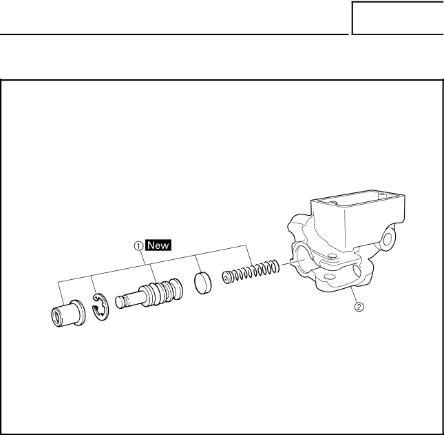
Brake Master Cylinder
Front Brake Master Cylinder
Removing the front brake master
Cylinder
Master cylinder
Disassembling the front brake
Assembling the Front Brake Master Cylinder
Checking the Master Cylinder
Installing the Front Brake Master Cylinder
Chas
Front Brake Caliper
Removing the front brake calipers
Calipers
Assembling the Front Brake
Calipers
Recommended brake component Replacement schedule Brake pads
Disassembling the Front Brake Calipers
Checking the Front Brake Calipers
Assembling the Front Brake Calipers
Installing the Front Brake Calipers
Fill Brake reservoir
Removing the rear brake lever
Removing the rear brake pedal
Removing the rear brake drum
Chas
Removing the Rear Brake
Checking the Rear Brake
Lithium-soap base grease
Installing the Rear Brake
Brake shoe lining thickness limit 2.0 mm 0.08
Brake drum inside diameter limit maximum 161 mm 6.34
Bolt brake shoe plate 28 Nm 2.8 m kg, 20 ft lb
Bolt camshaft lever Nm 0.9 m kg, 6.5 ft lb
Chas
Removing the handlebar
Cylinder Assembly
Brake Switch
Handlebar
Checking the Handlebar
Removing the Rear Brake Switch
Installing the Handlebar
Installing the Rear Brake Lever
Installing the Master Cylinder Assembly
Steering Stem
Removing the steering stem
Guide
Bearing Retainer
Checking the Steering Stem
Installing the Bearing Retainer
Installing the Cable Guide
Removing the Bearing Retainer
Knuckles
TIE Rods and Steering Knuckles
Removing the tie rods and steering
Knuckles
Chas
Removing the Steering Knuckles
Checking the TIE Rods
Checking the Steering Knuckles
Chas
Eye protection is recommended when using striking tools
Installing the TIE Rods
Shock absorbers
Removing the front arms and front
Absorber
Arms and Front Shock
Checking the Front Arms
Removing the Front Arms
Replacement steps
Checking the Front Shock Absorber
Installing the Front Arms and Front Shock Absorber
Nut 45 Nm 4.5 m kg, 32 ft lb
Nut 30 Nm 3.0 m kg, 22 ft lb
Swingarm
Removing the rear shock absorber
Swingarm
Housing
Removing the Swingarm
Nut swingarm 82 Nm 8.2 m kg, 59 ft lb
Checking the Rear Shock Absorber
Checking the Rubber Boot
Installing the Rubber Boot
Checking the Swingarm
Nut 63 Nm 6.3 m kg, 45 ft lb Loctite Bolt Loctite Nut
Installing the Rear Axle Housing
Electrical Components Elec
Checking a Switch
Checking a Switch Shown in the Manual
Example chart shows that
Elec +
Checking the Switch Continuity
Elec
Checking the Condition of the Bulbs
Types of Bulbs
Pocket tester YU-03112-C
Checking the Condition of the Bulb Sockets
Circuit Diagram
Standard spark plug
Troubleshooting
Procedure
Open-circuit voltage Or more at 20 C 68 F
Spark plug gap
Minimum spark gap 6.0 mm 0.24
Spark plug cap resistance 10 kΩ at 20 C 68 F
Primary coil resistance 18 ~ 0.28 Ω at 20 C 68 F
Both Meet Specification
Correct OUT of Specification
C0NTINUITY
Main switch Refer to Checking the Switches
Properly connect the ignition system Replace the CDI unit
Correct Poor Connection
System Electric Starting System Elec
If the Starter Motor Fails to Operate
Does not Turn
Turns
Incorrect Correct
Motor
Starter Motor
Removing the starter motor
Disassembling the starter motor
Checking the Starter Motor
Outside diameter 28 mm 1.10 Wear limit 27 mm 1.06
Mica undercut 0.7 mm 0.03
Assembling the Starter Motor
Brush length 12.5 mm 0.49 Wear limit 5 mm 0.20
Charging
Continuity No Continuity
If the Battery is not Charged
Charging voltage
Meets Specification
OUT Specification
OUT of Specification
Headlight fuse
If the Headlight AND/OR Taillight Fail to Come on
Correct Incorrect
Checking the Lighting System
Tester + lead → Blue lead 1 Tester lead → Black lead
Meets Specification No Continuity
Tester + lead → Blue terminal 1 Tester lead → Black terminal
Elec
Elec
Elec
EB806010
Properly connect the signal system
Checking the Signal System
If the neutral indicator light fails to come on
If the reverse indicator light fails to come on
Test Coolant temperature Thermo switch Continuity Step
Less than 120 ± 3 C 248 ± 5.4 F
235.4 F
BAD Condition
Good Condition
Correct
OUT of Specification Meets
System
Cooling
If the FAN Motor does not Move
Circuit breaker resistance Zero Ω at 20 C 68 F
Meets Specification Does not Turn
Less than 86 ± 3 C 186.8 ± 5.4 F
176 ± 5.4 F
Good
Properly connect the cooling system
System
If the Gear Motor Fails to Operate
Replace the on-command four-wheel drive switch
Correct Poor Connection
Electrical System
Fuel System
Poor Medium and HIGH-SPEED Performance
Compression System
Faulty Drive Train
Engine Operates but Machine will not Move
Hard Shifting
Shift Lever does not Move
Jumps OUT of Gear
Poor Speed Performance
Overheating
Poor Braking Effect
Bulb Burnt OUT
Malfunction
Unstable Handling
Headlight Dark
YFM400FAR Wiring Diagram
Shingai Iwata Shizuoka Japan