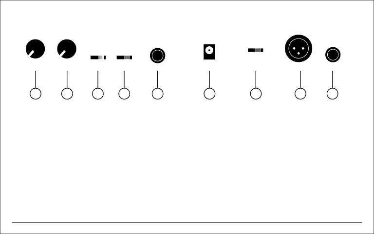
FRONT PANEL CONTROLS |
| REAR PANEL CONNECTIONS |
|
|
|
|
|
|
|
|
|
|
|
|
1 | 2 | 3 | 4 | 5 | 6 | 7 | 8 | 9 |
1.LO CONTOUR CONTROL: This control adjusts the amount of phase corrected bass frequencies.
2.PROCESS CONTROL: This control adjusts the amount of phase corrected treble frequencies.
3.BBE FUNCTION: This switch allows for the quick comparison of the processed and unprocessed sound.
4.INPUT PAD: This switch allows the user to select between an
instrument input (input impedance = 1 MEG OHMs), or a line level input (input impedance = 12k OHMs).
5.INPUT JACK: This is a 1/4” phone jack for signal insertion. Input signal can be from an instrument, or line level from a preamp. Connecting a 1/4” mono phono plug to this input activates the internal 9 volt battery and will power the
6.D.C. INLET: This jack is for connecting the VDC power source.
The 9 VDC power plug must be of the type where the positive voltage is on the outer ring.
7.GROUND LIFT: This switch is used to lift the units ground connec- tion from pin 3 the XLR balanced output.
8.BALANCED OUTPUT: This XLR jack provides a mic level, bal- anced output. Pin 2 being the ‘Hot’ pin. The
9.UNBALANCED OUTPUT: This 1/4” phone jack provides an unbalanced line level output.
NOTE: This unit may be powered by three (3) different modes.
1.Internal 9 volt battery.
2.9 VDC external power source.
3.48v phantom power source.
NOTE: When using phantom powering, XLR ground lift must be off.
BBE