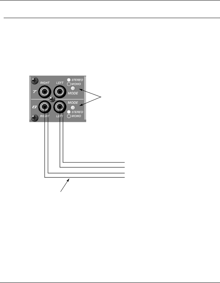
Peavey SMR 821 user manual Stereo Inputs, Unbalanced RCA connections

Page 9

Connections

Stereo Inputs

Channels 7 and 8 provide two individual inputs for each channel. These are intended for stereo use, as each input (Left, Right) has a fixed assignment to the Left and Right output buses. Additionally, a sum of both inputs is fed simultaneously to the Aux output bus. Although you cannot change the distribution of these inputs, you can determine if they are stereo or mono. The Mode Switch, when enabled, will sum both connectors, feeding both to the Left and Right outputs simultaneously. These con- nectors accept nominal levels of -10dBV.

The Mode switch selects either Stereo mode or Mono mode individ- ually for Channel 7 or 8. In the Stereo mode, the Left input signal feeds the Left mix bus and the Right input signal feeds the Right mix bus via the front panel Level Control. In the Mono mode, the summed Left and Right input signals feed both Left and Right mix buses. This allows for only one input to be used to feed the stereo mix buses. Additionally, it allows for Left and Right outputs of the source to be summed without a Y-cable. In either mode, a summed mono signal feeds the Aux mix bus.

Unbalanced RCA connections

Left Shield

Left “Hot” Audio

Right Shield

Right “Hot” Audio

The cabling for these connectors should be of the standard, consumer un-balanced shielded type. If you are using a 2-conductor shielded cable, make sure to connect the negative side of the signal to the shield. NOTE: Unbalanced signal sources should be located within approx- imately 6’ of the SMR-821.

Figure 3. RCA Input Connections

Peavey Electronics Corp

Page 9

Image 9
Contents SMRTM821 Page Thank You What’s In The Box? Description Features Front Panel Features Rear Panel Features Installation Audio Input ConnectionsBalanced Microphone or Line Level Input Un-Balanced Microphone or Line Level InputUnbalanced RCA connections Stereo InputsMaster Bus Output & Link Connections Audio Bus Outputs, Typical For Each BusMaster Bus & Mute Link Connections External Control Connections Remote Volume Control ConnectionsInput Channel Controls ConfigurationConfiguration Restaurant System FeaturesEmergency Page Source Hotel Meeting RoomsPresentation Room Stereo Loudspeakers Center System FeaturesBar Small House of Worship Plant Paging Office All Call Zone 1 Assembly PlantZone 2- Warehouse Shop Floor SupervisorBus Link CourtroomFrequently Asked Questions USA Tech Support Warranty RegistrationInstalling the Optional Microphone Input Transformers Optional FeaturesDefeat the functionality of the Channel 7/8 select switch Warranty altogetherCut Jumper Here Cut Resistor Here Channel Cut Jumper Here Channel 7/8 ModificationSMR 821 Functional Block Diagram SMR 821 Stereo MIC/LINE Program Mixer Specifications Dimensions H x W x D Weight Mounting ConnectionsInput Sensitivity Output Specifications NoiseGain Page Architectural Acoustics Product of Peavey Electronics Corporation