Miller Electric CST 250 Selecting and Preparing Tungsten Electrode, Selecting Tungsten Electrode

Page 31

SECTION 7 − SELECTING AND PREPARING TUNGSTEN

ELECTRODE

gtaw 7/97

NOTE

For additional information, see your distributor for a handbook on the Gas Tungsten Arc Welding (GTAW) process.Wear clean gloves to prevent contamination of tungsten electrode.

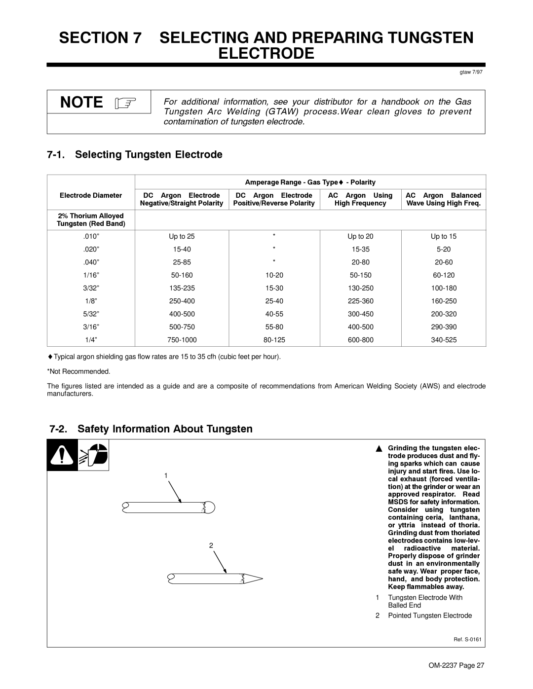
7-1. Selecting Tungsten Electrode


Amperage Range - Gas Type- Polarity


Electrode Diameter

DC − Argon − Electrode

DC − Argon − Electrode

AC − Argon − Using

AC − Argon − Balanced


Negative/Straight Polarity

Positive/Reverse Polarity

High Frequency

Wave Using High Freq.


2% Thorium Alloyed


Tungsten (Red Band)


.010”

Up to 25

*

Up to 20

Up to 15

.020”

15-40

*

15-35

5-20

.040”

25-85

*

20-80

20-60

1/16”

50-160

10-20

50-150

60-120

3/32”

135-235

15-30

130-250

100-180

1/8”

250-400

25-40

225-360

160-250

5/32”

400-500

40-55

300-450

200-320

3/16”

500-750

55-80

400-500

290-390

1/4”

750-1000

80-125

600-800

340-525


Typical argon shielding gas flow rates are 15 to 35 cfh (cubic feet per hour).

*Not Recommended.

The figures listed are intended as a guide and are a composite of recommendations from American Welding Society (AWS) and electrode manufacturers.

7-2. Safety Information About Tungsten

Y Grinding the tungsten elec-


trode produces dust and fly-


ing sparks which can cause

1

injury and start fires. Use lo-

cal exhaust (forced ventila-


tion) at the grinder or wear an


approved respirator. Read


MSDS for safety information.


Consider

using

tungsten


containing ceria,

lanthana,


or yttria

instead of thoria.


Grinding dust from thoriated

2

electrodes contains low-lev-

el radioactive

material.


Properly dispose of grinder


dust in an environmentally


safe way. Wear proper face,


hand, and body protection.


Keep flammables away.

1

Tungsten Electrode With


Balled End


2

Pointed Tungsten Electrode

Ref. S-0161

OM-2237 Page 27

Image 31
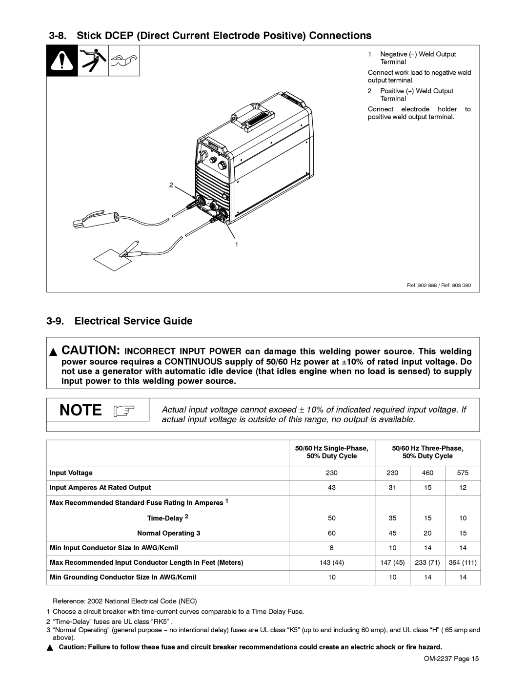
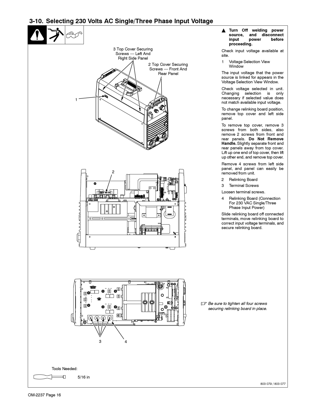
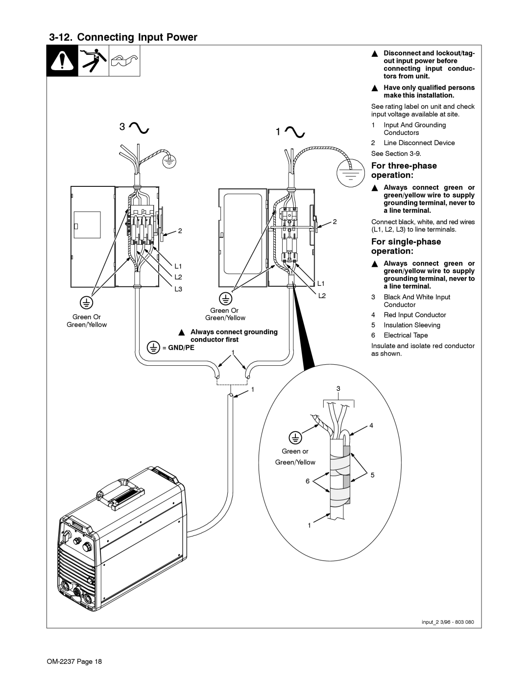
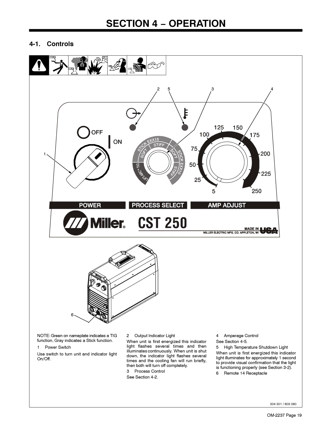
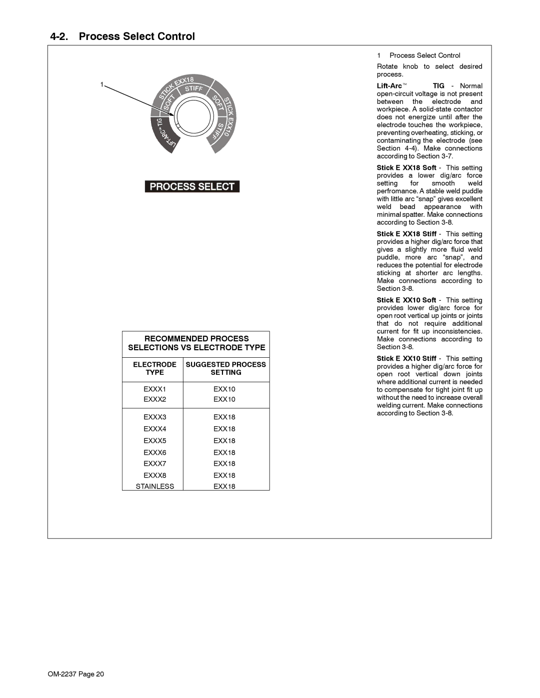
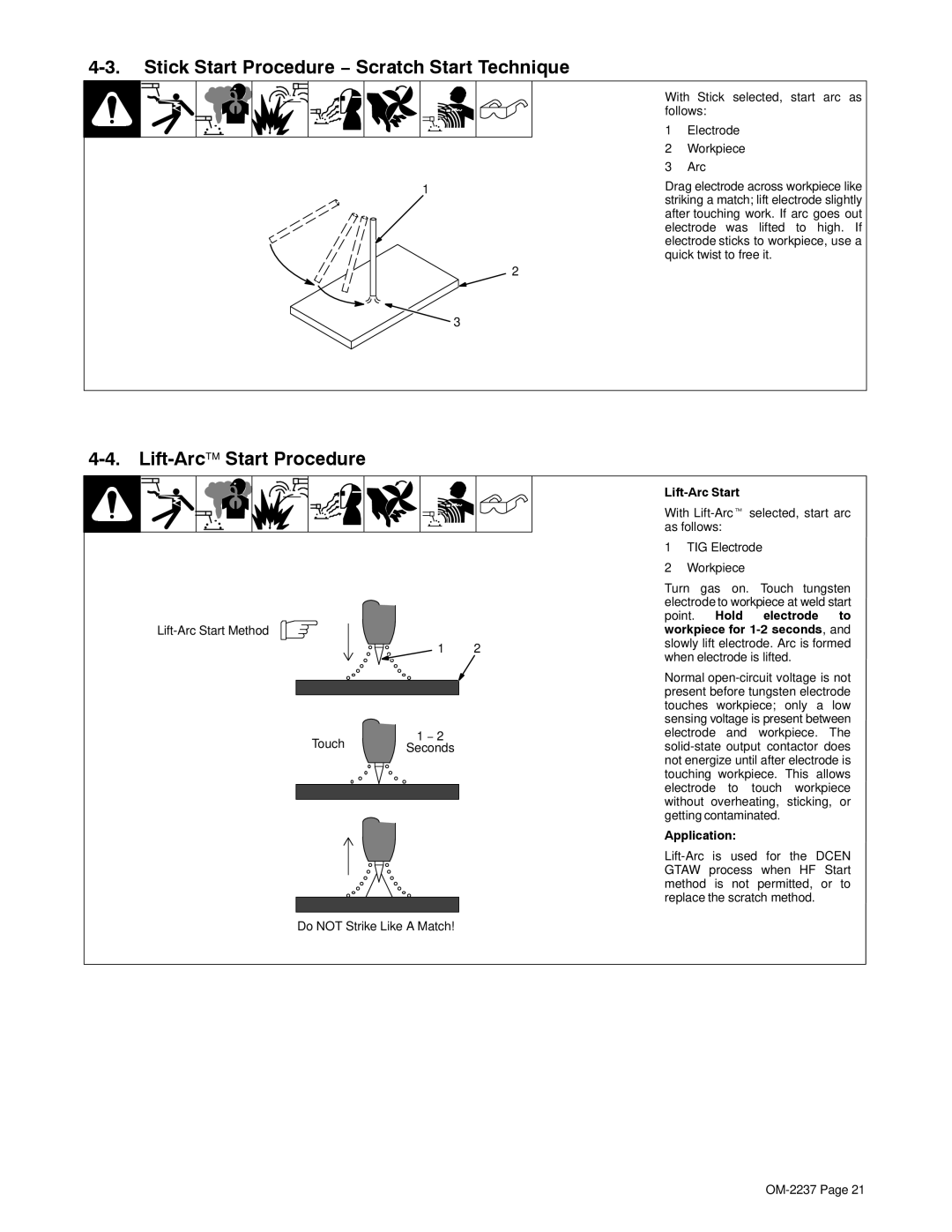
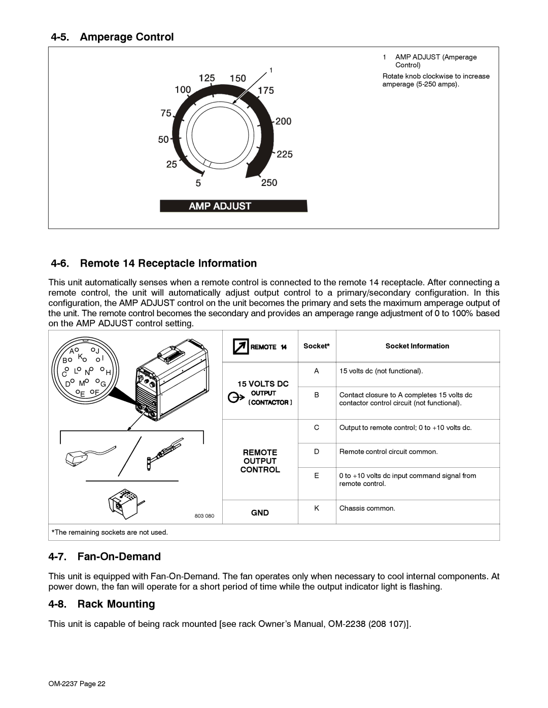
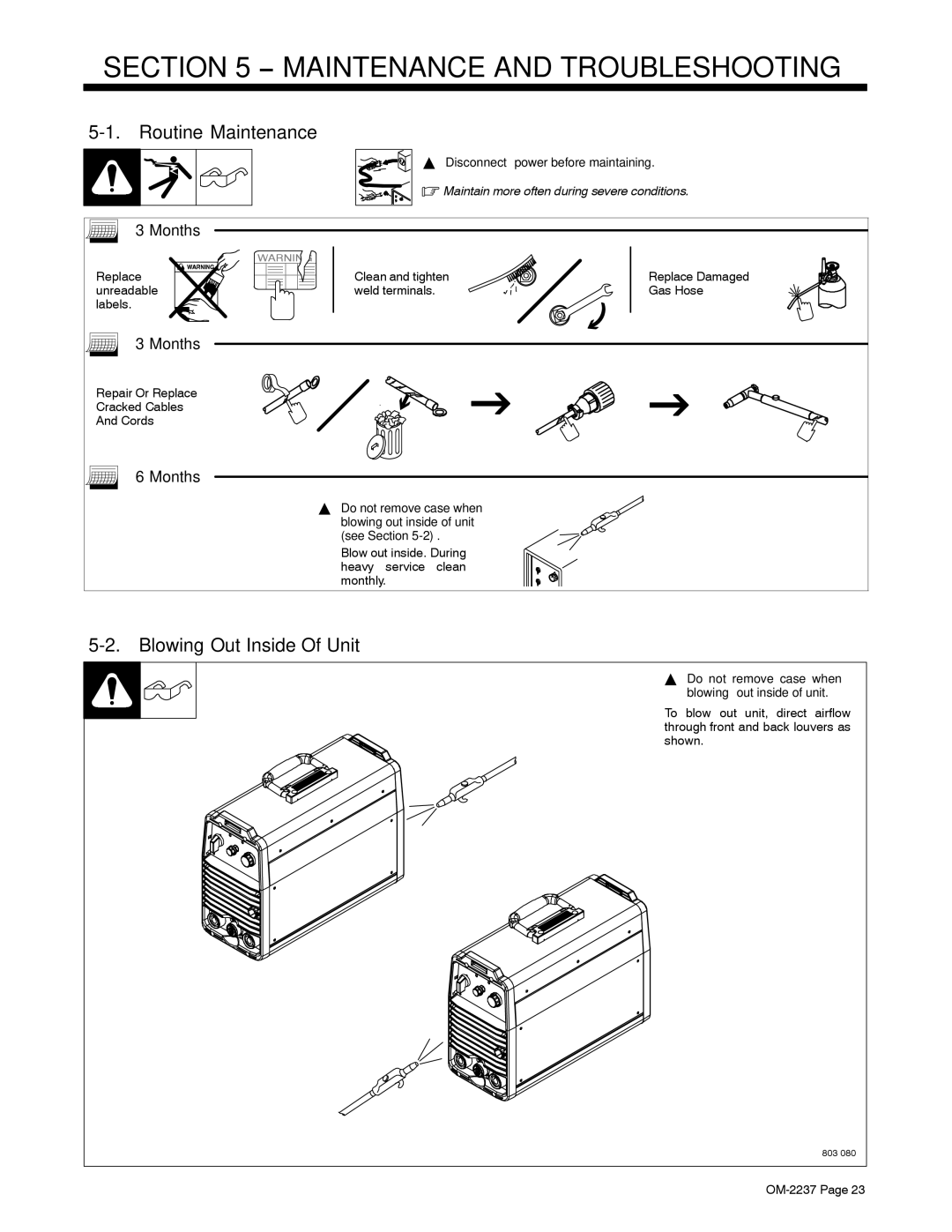
Contents Processes OM-2237 206 035HDescription From Miller to You Table of Contents Page Electric Shock can kill Symbol UsageMarks a special safety message Arc Welding HazardsBuildup of GAS can injure or kill ARC Rays can burn eyes and skinWelding can cause fire or explosion Flying Metal can injure eyesCalifornia Proposition 65 Warnings EMF Information Principal Safety StandardsAbout Pacemakers LES Fumées ET LES GAZ peuvent être dangereux Signification des symboles− Consignes DE Sécurité − À Lire Avant Utilisation LES Décharges Électriques peuvent être mortellesLE Bruit peut affecter l’ouïe LE Soudage peut causer un incen- die ou une explosionLES Particules Projetées peu- vent blesser les yeux LES Pièces Chaudes peuvent cau- ser des brûlures gravesLES Pièces Mobiles peuvent cau- ser des blessures Risque D’INCENDIE OU D’EXPLOLA Chute DE L’APPAREIL peut blesser ’EMPLOI Excessif peut FaireInformation sur les champs électromagnétiques Principales normes de sécuritéConsignes relatives aux stimulateurs cardiaques Specifications − InstallationDuty Cycle And Overheating 100 150 200 250 300 350 Stick Smaw Volt-Ampere CurvesAmps TIG Gtaw Volt-Ampere CurveSelecting a Location Dimensions And WeightLocation And Airflow Terminals Amperes Weld Output Terminals And Selecting Cable Sizes150 ft 200 ft 250 ft 350 ft 400 ft 45 m 60 m 70 m 90 m 105 m 120 mPositive + Weld Output Terminal Input Voltage Electrical Service Guide50/60 Hz Single-Phase 50/60 Hz Three-Phase Stick Dcep Direct Current Electrode Positive ConnectionsSelecting 230 Volts AC Single/Three Phase Input Voltage Relinking Board Connection For 460 575 VAC Input Power Selecting 460 575 Volts AC Three Phase Input Voltage= GND/PE Connecting Input PowerFor three-phase operation For single-phase operationControls − OperationLift-ArctTIG Normal Process Select ControlApplication Stick Start Procedure − Scratch Start TechniqueLift-ArcStart Procedure Lift-Arc StartRack Mounting Amperage ControlRemote 14 Receptacle Information Fan-On-DemandMonths − Maintenance and TroubleshootingRoutine Maintenance Blowing Out Inside Of UnitTrouble Possible Causes Remedy TroubleshootingUse proper size and type of weld cable see Section Circuit Diagram − Electrical Diagrams− Selecting and Preparing Tungsten Electrode Safety Information About TungstenSelecting Tungsten Electrode Tungsten Electrode OM-2237 Main Assembly − Parts ListCAPACITOR,ELCTLT 2400 UF 500 VDC can 2.5 DIA Panel, Front w/Components Panel, Rear w/Components Magnetics Subassembly Heat Sink Assembly, Output Diode Base Assembly Heat Sink Assembly, Input Page Support ServiceMiller Electric Mfg. Co Owner’s Record