Wheel Selection
Aluminum oxide and silicon carbide wheels are marked in a somewhat uniform manner by all the major manufacturers. Understanding these mark- ings will help you understand the capabilities of various wheels. Always refer to the manufactur- er’s grinding recommendations when selecting a wheel for your project.
The basic format for wheel numbering is:
Prefix | Abrasive | Grit | Grade | Bond | ||
|
| Type | Size |
|
| Type |
36 |
| A | 60 |
| L | V |
The most common abrasive types used are A for Aluminum Oxide and C for Silicon Carbide, and occasionally SG for seeded gel. The prefix is the manufacturer’s designation for a particular type.
The grit size is a number referring to the size of the abrasive grain in the wheel. The lower the number the coarser the wheel - 10 is a very coarse wheel for roughing and 220 is usually the upper range for fine finish work.
Grade is an indication of the hardness of the wheel, with A being softest to Z the hardest.
Bond Type refers to the type of bonding material used to hold the abrasive material. Most general purpose wheels will have a V indicating Vitrified clay is used, providing a high strength and good porosity. The other most common is B for resin where synthetic resins are used. These are used to grind cemented carbide and ceramic materials
There may be other numbers inserted which have meaning for a particular type of wheel. Refer to the manufacturer’s technical data for a complete explanation.
G5963 Surface Grinder
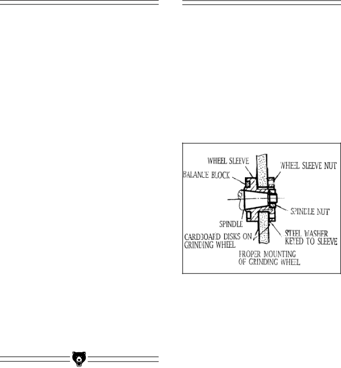
Wheel Mounting
Before mounting any wheel, check it for integrity by performing a “ring check”. Balance the wheel on one finger, then lightly tap the rim of the wheel with a piece of wood such as the handle of a hammer. The wheel should have a ringing or har- monic type of sound. If it responds with a dull thud it may indicate that the wheel has cracks. Do not use a wheel which is suspected of having cracks, or if there are visual chips, nicks or dents in the wheel surface. These discontinuities can lead to wheel failure where the wheel flies apart at operating speed. Always be sure to use a wheel which is rated for operating at speeds of 3450 RPM.