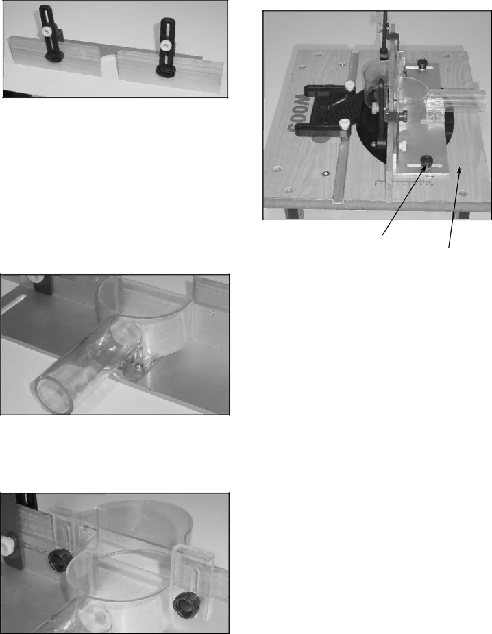
ii)Attach the two vertical clamps (13) to the vertical clamp supports using washer M5 (22) and knob M5x10mm (21).
v)Attach the completed fence unit to the table by insert- ing knob M6x16mm (24) with washer M6 (19) through the slot in the fence base into the threaded insert in the table top.
Fig.3
iii)Attach the transparent plastic dust chute (15) using two roundhead screws M5x10mm (23) with Washers M5 (22).
This dust chute is designed to be used with vacuum cleaners, using a 38mm hose, or dust extractors, using either a 50mm hose or 100mm hose with a reducing cone, fitting either inside or over the outside of the chute accordingly. It will sometimes be necessary to obtain a reducing cone to match your hose to the outlet.
If you are intending to use the router table without a dust collector it is better to leave off the dust chute to avoid a build up of wood shavings.
Fig.4
iv)Attach the transparent plastic cutter Guard (10) to the fence using knob M5x10mm (21) and washer M5 (22).
Fig.6
Position 1
Position 2
There are two sets of threaded inserts in the table. The choice of which to use will depend on the type of job to be performed; Position 1 allows the fence to be set at the front of the cutter aperture for making shallow cuts or edge moulding. Position 2 allows the fence to be set fur- ther back from the cutter for operations such as trench- ing.
ASSEMBLE THE FINGER PRESSURE
The finger pressure unit is already assembled and sim- ply needs fitting to the table. It locks into the aluminium channel which runs across the front of the table using the two knobs (20).
Fig.5