|
|
Integrated Furnace Control | |
| INSTALLATION INSTRUCTIONS |
|
|
Operator: Save these instructions for future use!
FAILURE TO READ AND FOLLOW ALL INSTRUCTIONS CAREFULLY BEFORE INSTALLING OR OPERATING THIS CONTROL COULD CAUSE PERSONAL INJURY AND/OR PROPERTY DAMAGE.
DESCRIPTION
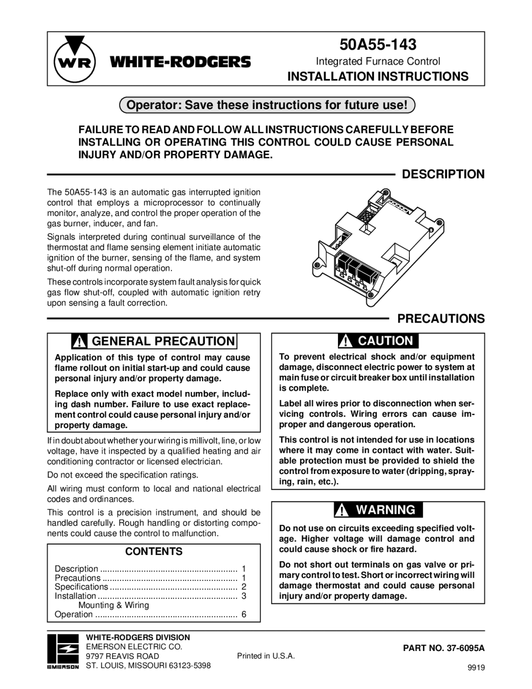
The
Signals interpreted during continual surveillance of the thermostat and flame sensing element initiate automatic ignition of the burner, sensing of the flame, and system
These controls incorporate system fault analysis for quick gas flow
PRECAUTIONS
! GENERAL PRECAUTION |
Application of this type of control may cause flame rollout on initial
Replace only with exact model number, includ- ing dash number. Failure to use exact replace- ment control could cause personal injury and/or property damage.
If in doubt about whether your wiring is millivolt, line, or low voltage, have it inspected by a qualified heating and air conditioning contractor or licensed electrician.
Do not exceed the specification ratings.
All wiring must conform to local and national electrical codes and ordinances.
This control is a precision instrument, and should be handled carefully. Rough handling or distorting compo- nents could cause the control to malfunction.
CONTENTS |
|
Description | 1 |
Precautions | 1 |
Specifications | 2 |
Installation | 3 |
Mounting & Wiring |
|
Operation | 6 |
!CAUTION
To prevent electrical shock and/or equipment damage, disconnect electric power to system at main fuse or circuit breaker box until installation is complete.
Label all wires prior to disconnection when ser- vicing controls. Wiring errors can cause im- proper and dangerous operation.
This control is not intended for use in locations where it may come in contact with water. Suit- able protection must be provided to shield the control from exposure to water (dripping, spray- ing, rain, etc.).
!WARNING
Do not use on circuits exceeding specified volt- age. Higher voltage will damage control and could cause shock or fire hazard.
Do not short out terminals on gas valve or pri- mary control to test. Short or incorrect wiring will damage thermostat and could cause personal injury and/or property damage.
| |
EMERSON ELECTRIC CO. | PART NO. |
9797 REAVIS ROAD | Printed in U.S.A. |
ST. LOUIS, MISSOURI | 9919 |


