Presonus Audio electronic
E5, E8
owner manual
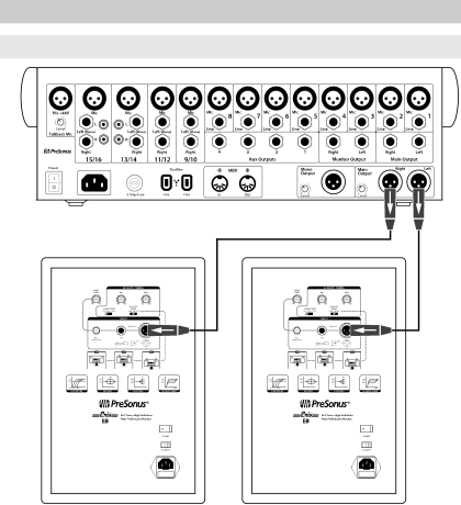
Hookup Diagrams Basic Setup
Page 9
2
Hookup
Eris™ Series E5 and E8
2.2
Hookup Diagrams
Owner’s Manual
2.2
Hookup Diagrams
2.2.1
Basic Setup
100 - 240 VAC
50-60Hz
On
Eris E8
Page 8
Page 10
Image 9
Page 8
Page 10
Contents
Eris Series E5 / E8
Parts INSIDE. Refer Servicing to Qualified Personnel
Important Safety Instructions
Page
Table of Contents
Introduction
Overview
What is in the box
Summary of Eris E5/E8 Features
Rear Panel Connections and Controls
Hookup
Acoustic Tuning Controls
Power
Hookup Diagrams Basic Setup
Advanced Setup with Speaker Switching
Tutorials
Monitor Placement
Equalizer Setting Suggestions
Input Gain Setting
Acoustic Space Setting Suggestions
Acoustic Space Setting Suggestions
Resources
Technical Specifications
Power
Troubleshooting
PreSonus Limited Warranty
PreSonus Audio Electronics, Inc Florida Blvd
Rice Dressing
Florida Boulevard Baton Rouge Louisiana 70806 USA
Related pages
How to troubleshoot issues with the
MGE Galaxy 5000
internal components?
Top
Page
Image
Contents