
4.Mark screw positions for front and rear connectors and
tape ¼" from drill tip to set drilling depth. Use care not to drill through tabletop.
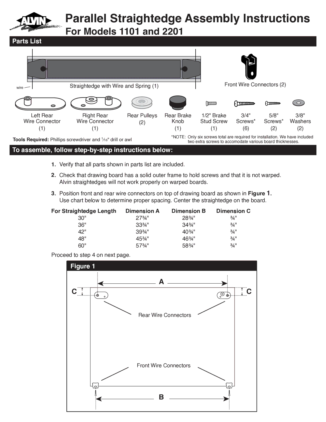
5.Fasten front connectors to front edge of board as shown in Figure 2 using ¾" screws. Fasten screws half way. Do not fully tighten.
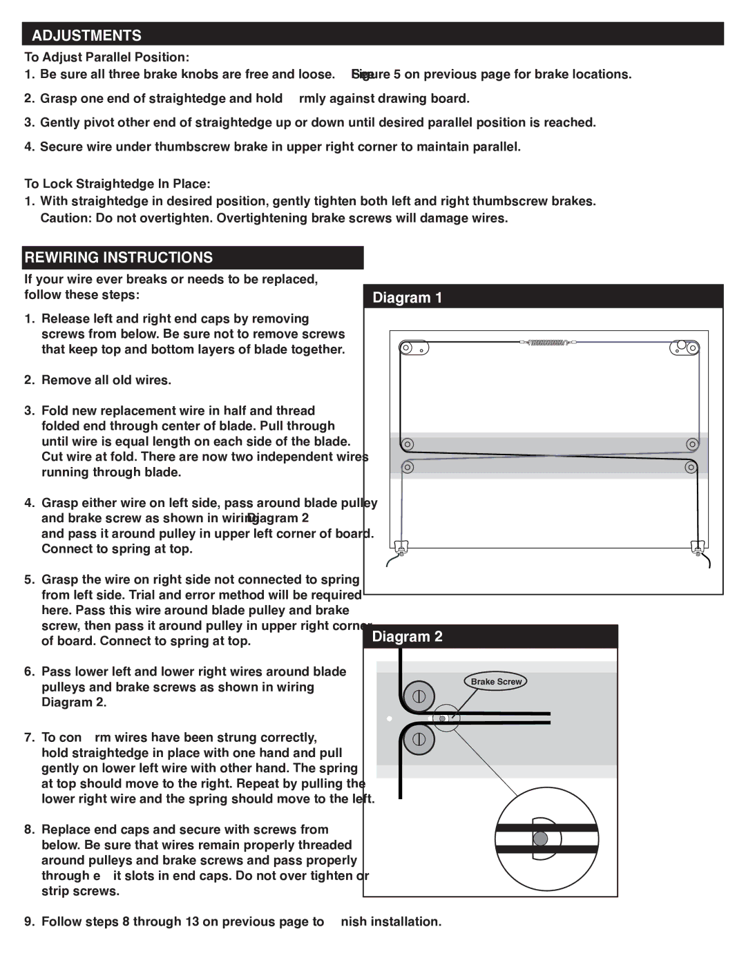
6.Assemble right rear connector as shown in Figure 3 and fasten to board. Select screw length based upon board thickness.* Fasten screws securely.
*For board thicknesses of 5/8" or less:
If your board is 5⁄8" thick or less please use the
5⁄8" screws in place of the ¾" screws as shown in Figures 3 and 4. Do not use ¾" screws included with hardware kit since they might break through bottom of board.
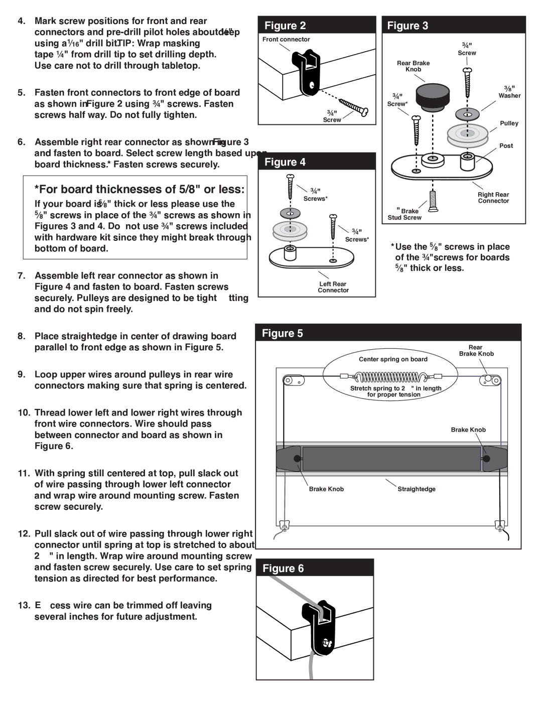
7.Assemble left rear connector as shown in Figure 4 and fasten to board. Fasten screws securely. Pulleys are designed to be tight fitting and do not spin freely.
Figure 2
Front connector
¾"
Screw
Figure 4
![]()
![]() ¾"
¾"
Screws*
![]()
![]() ¾"
¾"
Screws*
Left Rear
Connector
Figure 3
| ¾" |
| Screw |
Rear Brake |
|
Knob |
|
¾" | 3⁄8" |
Washer | |
Screw* |
|
| Pulley |
| Post |
Right Rear
Connector
½" Brake
Stud Screw
*Use the 5⁄8" screws in place of the ¾"screws for boards 5⁄8" thick or less.
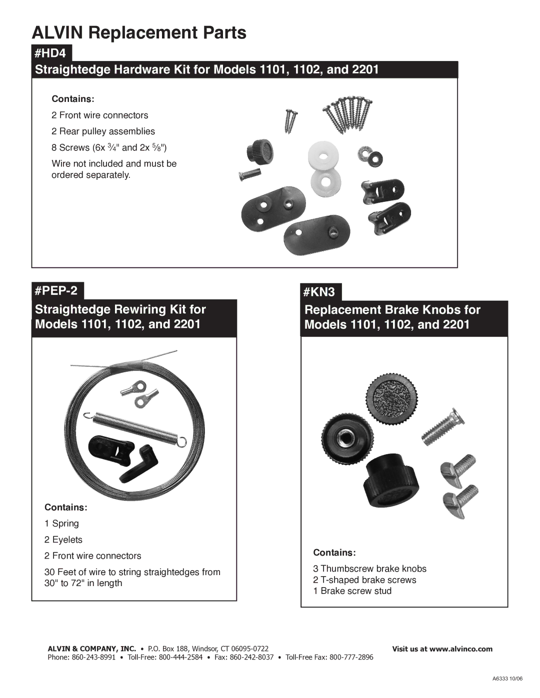
8. | Place straightedge in center of drawing board |
| parallel to front edge as shown in Figure 5. |
9. | Loop upper wires around pulleys in rear wire |
| connectors making sure that spring is centered. |
Figure 5
Center spring on board
Rear
Brake Knob
10. | Thread lower left and lower right wires through |
| front wire connectors. Wire should pass |
| between connector and board as shown in |
| Figure 6. |
11. | With spring still centered at top, pull slack out |
| of wire passing through lower left connector |
| and wrap wire around mounting screw. Fasten |
| screw securely. |
12. | Pull slack out of wire passing through lower right |
| connector until spring at top is stretched to about |
| 2½" in length. Wrap wire around mounting screw |
| and fasten screw securely. Use care to set spring |
| tension as directed for best performance. |
13. | Excess wire can be trimmed off leaving |
| several inches for future adjustment. |
Stretch spring to 2½" in length
for proper tension
Brake Knob
Brake Knob | Straightedge |
Figure 6