3CR100AV97 specifications
The 3Com 3CR100AV97 is a prominent model in the realm of networking devices, specifically designed to enhance connectivity solutions for both homes and small businesses. This versatile router stands out due to its robust feature set and reliability, making it an ideal choice for users seeking efficient networking performance.One of the main features of the 3CR100AV97 is its advanced wireless technology, which complies with the 802.11g standard. This allows for wireless transmission speeds of up to 54 Mbps, making it suitable for activities like streaming video, online gaming, and general web browsing. With a range that can cover an average-sized home or small office, users are provided with the flexibility to connect multiple devices without compromising on speed or performance.
Another significant aspect of the 3CR100AV97 is its integrated security features. The router supports various encryption protocols, including WEP, WPA, and WPA2, ensuring that users' networks remain protected against unauthorized access. This security functionality is crucial in today’s digital landscape, where the threats of cyberattacks are ever-present. Users can rest assured that sensitive personal and business information is safeguarded.
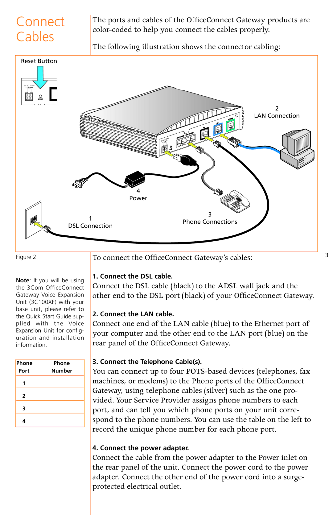
The 3Com 3CR100AV97 also boasts a simple setup process. With its user-friendly interface, even those with minimal technical knowledge can easily configure their network settings. The device usually comes with a quick start guide that walks users through the process, allowing for a swift and hassle-free installation. Additionally, the router features built-in DHCP, which dynamically assigns IP addresses, further simplifying network management.
Another notable characteristic is the Ethernet ports available on the 3CR100AV97. The router is equipped with several fast Ethernet ports, which support wired connections and ensure stable internet access for devices that require it. This is particularly beneficial for businesses that rely on reliable connectivity for desktop computers, printers, and other networked equipment.
Finally, the 3Com 3CR100AV97 is designed with durability in mind. Its solid build quality ensures longevity, reducing the need for frequent replacements. This reliability, combined with its robust performance features, makes it a valuable investment for users seeking to enhance their network infrastructure without incurring excessive costs.
In conclusion, the 3Com 3CR100AV97 router is a well-rounded device that successfully combines speed, security, and ease of use. Its wireless capabilities, robust security protocols, straightforward setup, and durable design make it an excellent choice for users looking for a dependable networking solution.

