NCG-PLM, PLM Series specifications
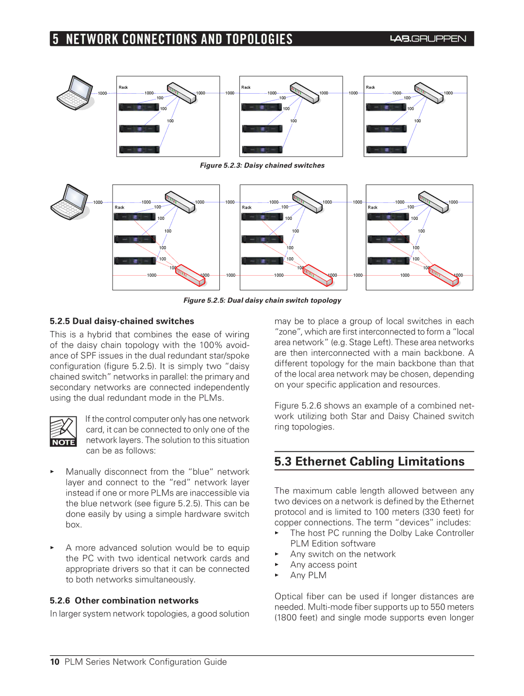
The 3Com NCG-PLM, PLM Series is a notable product line from 3Com Corporation designed to enhance network management and provide a robust infrastructure for businesses. This series is centered around providing seamless connectivity and efficient network performance while supporting a variety of applications and services.One of the main features of the PLM Series is its advanced network management capabilities. The series offers a comprehensive suite of management tools that facilitate easy monitoring and configuration of network devices. This enables IT administrators to gain visibility into network performance, troubleshoot issues, and manage bandwidth effectively. The user-friendly interface simplifies these processes, allowing for quick adjustments and ensuring optimal functionality.
The PLM Series integrates cutting-edge technologies to support high-speed connectivity and data transfer. With support for Gigabit Ethernet, the series ensures that data can be transferred rapidly across networks, meeting the growing demands of modern applications and user expectations. Such speed is crucial for businesses that rely on data-intensive applications, video conferencing, and cloud services.
Furthermore, one of the hallmark characteristics of the 3Com NCG-PLM Series is its reliability and scalability. Designed to accommodate increasing network demands, the devices within this series can easily expand to support additional users and devices. This scalability ensures that organizations can grow without the need for extensive overhauls of their existing infrastructure.
Security is another paramount feature of the PLM Series. It employs various security protocols to protect sensitive data and maintain the integrity of the network. This includes measures against unauthorized access, ensuring that only authenticated devices and users can connect to the network. This commitment to security is critical in today’s climate where cyber threats are ever-evolving.
The PLM Series is also designed with energy efficiency in mind. The devices consume less power without compromising performance, thereby supporting sustainability initiatives within organizations. This energy-efficient design can result in significant cost savings on power consumption over time.
In summary, the 3Com NCG-PLM, PLM Series stands out for its advanced network management tools, high-speed connectivity, reliability, scalability, strong security measures, and energy efficiency. These attributes make it an ideal choice for businesses seeking to optimize their network infrastructure and cope with the increasing demands of modern digital operations.

