The universal 3M brand Fiber Optic Connector Crimp Tool is designed to be used with all 3M
Die | Cavity | Application |
Marking | Marking |
|
|
|
|
|
|
|
BC/ST | .151 | ST* (BAYONET), |
| .178 | TECS (SMA) 200/230 |
| .213 | PROTECTIVE |
|
|
|
SC |
| SPLICE |
| SC and | |
| .120 | 2.4mm CABLE CRIMP RING |
| .137 | 3.0mm CABLE CRIMP RING |
| .190 | KEVLAR CRIMP AREA |
|
|
|
|
|
|
PPST |
| ST ( PUSH PULL) |
|
|
|
| .120 | 2.4mm CABLE CRIMP RING |
| .137 | 3.0mm CABLE CRIMP RING |
| .226 | KEVLAR CRIMP AREA |
|
|
|
Installing the Dies in the Base Tool
1.Select the appropriate set of dies as identified in the table above.
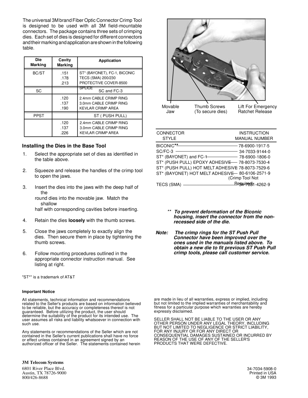
2.Squeeze and release the handles of the crimp tool to open the jaws.
3.Insert the dies into the jaws with the deep half of the
round dies into the movable jaw. Match the shallow
half with corresponding cavities before inserting.
4.Retain the dies loosely with the thumb screws.
5.Close the jaws completely to exactly align the dies. Then secure them in place by tightening the thumb screws.
6.Follow mounting procedures outlined in the appropriate connector instruction manual. See listing at right.
"ST*" is a trademark of AT&T
Important Notice
All statements, technical information and recommendations related to the Seller's products are based on information believed to be reliable, but the accuracy or completeness thereof is not guaranteed. Before utilizing the product, the user should determine the suitability of the product for its intended use. The user assumes all risks and liability whatsoever in connection with such use.
Any statements or recommendations of the Seller which are not contained in the Seller's current publications shall have no force or effect unless contained in an agreement signed by an authorized officer of the Seller. The statements contained herein
Movable | Thumb Screws |
|
| Lift For Emergency | ||||
Jaw | (To secure dies) |
|
| Ratchet Release | ||||
|
|
|
|
|
|
| ||
CONNECTOR |
|
|
|
|
| INSTRUCTION | ||
STYLE |
|
|
| MANUAL NUMBER | ||||
|
|
|
|
|
|
| ||
BICONIC** |
|
|
|
|
| |||
|
|
|
|
|
|
| ||
|
|
|
|
|
|
| ||
ST* (BAYONET) and |
|
| ||||||
ST* (PUSH PULL) EPOXY ADHESIVE |
|
|
| |||||
|
|
| ||||||
ST* (PUSH PULL) HOT MELT ADHESIVE | ||||||||
ST* (BAYONET) HOT MELT ADHESIVE |
|
| ||||||
|
| |||||||
|
|
| (Crimp Tool Not | |||||
TECS (SMA) |
|
|
|
| Required) | |||
|
|
|
|
| ||||
|
|
|
|
| ||||
**To prevent deformation of the Biconic housing, insert the connector from the non- recessed side of the die.
Note: The crimp rings for the ST Push Pull Connector have been improved over the ones used in the manuals listed above. To obtain a new die to fit previous ST Push Pull crimp tools, please call customer service.
are made in lieu of all warranties, express or implied, including but not limited to the implied warranties of merchantability and fitness for a particular purpose which warranties are hereby expressly disclaimed.
SELLER SHALL NOT BE LIABLE TO THE USER OR ANY OTHER PERSON UNDER ANY LEGAL THEORY, INCLUDING BUT NOT LIMITED TO NEGLIGENCE OR STRICT LIABILITY, FOR ANY INJURY OR FOR ANY DIRECT OR CONSEQUENTIAL DAMAGES SUSTAINED OR INCURRED BY REASON OF THE USE OF ANY OF THE SELLER'S PRODUCTS THAT WERE DEFECTIVE.
3M Telecom Systems |
|
6801 River Place Blvd. | |
Austin, TX | Printed in USA |
© 3M 1993 |