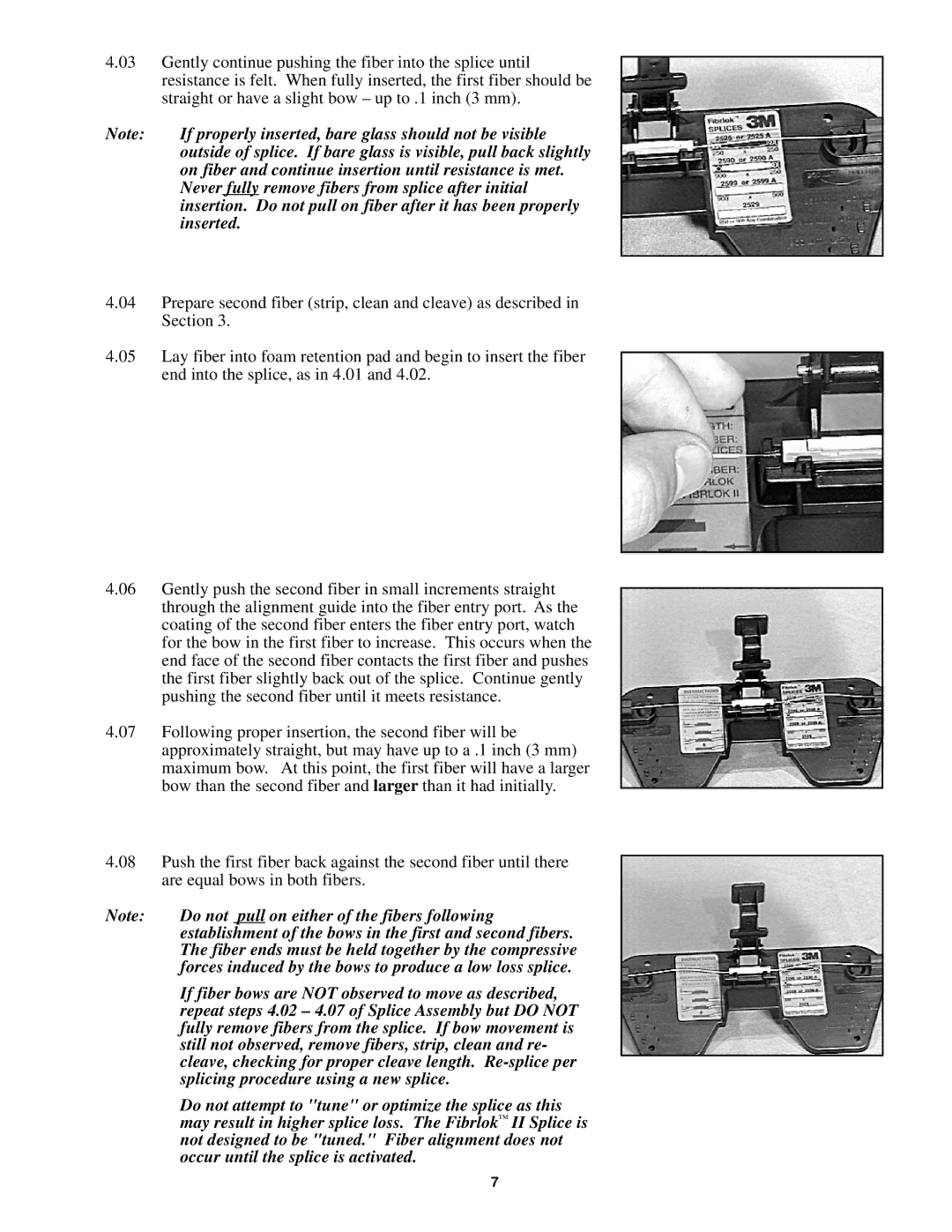
II 2529 specifications
3M II 2529 is a state-of-the-art adhesive tape developed to meet the diverse needs of various industries. This versatile product is known for its impressive adhesion properties, durability, and a range of innovative features that set it apart from conventional adhesive tapes.One of the main features of the 3M II 2529 is its exceptional conformability. The tape is designed to easily adhere to irregular surfaces, making it ideal for applications that require precision and reliability. Whether it is used in automotive, aerospace, or manufacturing sectors, the tape ensures a strong bond that can withstand demanding environments. Its flexibility allows it to conform to curves, edges, and protruding surfaces without losing its adhesion strength.
The technology behind 3M II 2529 incorporates advanced acrylic adhesive, which enhances its overall performance. The adhesive provides superior bonding capabilities while maintaining high resistance to temperature fluctuations, UV light, and moisture. This makes the tape suitable for both indoor and outdoor applications, ensuring that it remains effective under various environmental conditions.
Another significant characteristic of the 3M II 2529 is its excellent shear strength. This feature is vital in applications where the tape is subjected to load and stress over time. The tape's ability to resist slippage or creep, even when exposed to high pressure, ensures long-lasting performance, reducing the need for frequent replacements. This durability translates into cost savings for businesses, allowing them to operate more efficiently.
The 3M II 2529 is also known for its clean removal properties. It can be removed without leaving a sticky residue, making it an ideal choice for temporary bonding or masking applications. This feature is particularly beneficial in industries where surface cleanliness is crucial, such as electronics manufacturing and automotive assembly.
In addition to its physical properties, the 3M II 2529 is available in various widths and lengths, allowing for customization based on specific project requirements. This adaptability makes it a go-to solution for professionals across multiple sectors, as they can easily find a version of the tape that aligns perfectly with their needs.
In conclusion, the 3M II 2529 adhesive tape is a multifunctional product that stands out for its conformability, advanced adhesive technology, shear strength, and clean removal features. Its versatility allows it to be used across numerous applications, providing an effective, reliable solution for professionals in various fields. Whether for structural bonding, mounting, or masking, 3M II 2529 is a trusted choice that consistently delivers outstanding performance.

