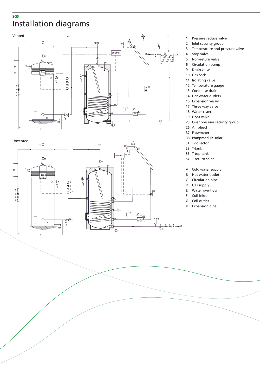
SGS - 30, SGS - 50, SGS - 28, SGS - 60 specifications
A.O. Smith is a well-known name in the water heater industry, recognized for its commitment to innovation and quality. Among its impressive lineup of products are the SGS-50, SGS-28, SGS-60, and SGS-30 water heaters. Each model is designed with unique features and advanced technologies to meet varying customer needs.The SGS-50 is a robust water heater designed to provide reliable performance for medium to large households. Featuring a 50-gallon tank, it is equipped with an advanced insulation system that minimizes heat loss and enhances energy efficiency. The SGS-50 is powered by high-efficiency burners that heat water quickly, ensuring you have a constant supply of hot water for showers, dishwashing, and laundry. Its durable construction includes a glass-lined tank to prevent corrosion, further extending its lifespan.
The SGS-28 is ideal for smaller households or apartments where space is at a premium. With a 28-gallon capacity, this compact water heater is still packed with features. It utilizes A.O. Smith’s patented technology for quicker recovery rates, meaning you won't have to wait long for hot water. The SGS-28 also offers excellent energy savings, making it an economical choice for budget-conscious consumers.
For larger families or high-demand settings, the SGS-60 model stands out with its 60-gallon capacity. Designed for maximum efficiency, it incorporates smart technology that automatically adjusts the heating cycle based on hot water usage patterns. This feature helps reduce energy costs without sacrificing performance. Additionally, the SGS-60 is outfitted with multiple safety features, including a temperature and pressure relief valve, ensuring a secure operation.
Lastly, the SGS-30 serves as a versatile option between the smaller SGS-28 and the larger SGS-50. Sporting a 30-gallon tank, it offers an excellent balance of size and efficiency. Like its A.O. Smith counterparts, the SGS-30 comes equipped with energy-efficient burners and enhanced insulation, providing quick heating capabilities and a reliable supply of hot water for various household needs.
In summary, A.O. Smith's SGS series of water heaters—including the SGS-50, SGS-28, SGS-60, and SGS-30—showcases a commitment to quality, efficiency, and customer satisfaction. Each model features advanced technologies tailored to specific household requirements, ensuring that A.O. Smith remains a trusted choice for hot water solutions in homes and businesses alike.

