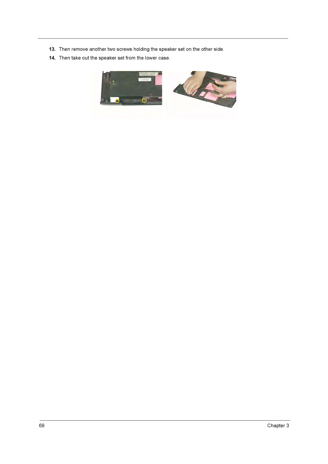
Manuals
/
Brands
/
Computer Equipment
/
Laptop
/
Acer
/
Computer Equipment
/
Laptop
Acer
1690, 3510
- page 76
1
76
125
125
Download
125 pages, 4.28 Mb
69
Chapter 3
13.
Then remove another two screws holding the speaker set on the other side.
14.
Then take out the speaker
set from the lower case.
Contents
Main
Page
Copyright
Disclaimer
Conventions
Preface
Table of Contents
Chapter 1 System Specifications 1
Chapter 2 System Utilities 45
Chapter 3 Machine Disassembly and Replacement 56
Page
System Specifications
Chapter 1
Features
Performance
Memory
Audio
Storage
Communication
I/O Ports
Battery
Page
Page
Page
6Chapter 1
Block Diagram
REV.C
NEW CARD
1.5V / 1.05V / 1.8V
LVDS
TV-OUT
Outlook View
Open View
Just for Starters...
Front Panel
"Launch keys" on page 10
# Icon Item Description
# Item Description
"Launch keys" on page 10
Left View
Right View
Page
Page
Using the Keyboard
Lock keys
Embedded Numeric Keypad
Desired action Num Lock on Num Lock off Fn
Indicators
Page
Windows Keys
Launch Keys
Launch key Default application
Hot Keys
Fn
Special Keys
Page
Using System Utilities
Acer eManager
Launch keys on page 20
Acer eSetting Acer ePresentation Acer ePowerManagement Acer eRecovery
Page
Page
Touchpad
Touchpad Basics
Page
Page
Hardware Specifications and Configurations
Page
Page
Page
Page
Page
Dimensions and Weight
Page
Page
Page
Page
Page
Page
Page
Page
Storage
Page
System Utilities
Chapter 2
BIOS Setup Utility
Information
Main
Page
Advanced
Page
Security
Set Supervisor/User Password
Page
Boot
Exit
Chapter 3
Machine Disassembly and Replacement
General Information
Before You Begin
IO Bezel Battery
Chapter 3 58
59 Chapter 3
Disassembly Procedure Flowchart
Chapter 3 60
Screw List
Page
Page
Removing the Thermal Module and CPU
Removing the ODD Module
Removing the LCD Module
Disassembling the Main Unit
Separate the Main Unit Into the Upper and the Lower Case Assembly
Disassembling the Upper Case Assembly
Disassembling the Lower Case Assembly
Page
Disassembling the LCD Module
Page
Disassembling the External Modules
Disassembling the Optical Drive Module
Page
System Check Procedures
External Diskette Drive Check
External CD-ROM Drive Check
Keyboard or Auxiliary Input Device Check
Memory check
Power System Check
Check the Power Adapter
Check the Battery Pack
Touchpad Check
Power-On Self-Test (POST) Error Message
Chapter 4 79
Index of Error Messages
Error Code List
80 Chapter 4
Chapter 4 81
82 Chapter 4
POST Code
Chapter 4 83
Index of Symptom-to-FRU Error Message
LCD-Related Symptoms
Indicator-Related Symptoms
Power-Related Symptoms
84 Chapter 4
PCMCIA-Related Symptoms
Memory-Related Symptoms
Speaker-Related Symptoms
Power Management-Related Symptoms
Chapter 4 85
Peripheral-Related Symptoms
Keyboard/Touchpad-Related Symptoms
Modem-Related Symptoms
Power Management-Related Symptoms
Page
Undetermined Problems
Page
Page
Page
Page
Page
Page
Page
Page
Page
Page
Page
FRU (Field Replaceable Unit) List
Chapter 6
Page
Chapter 6 101
102 Chapter 6
Chapter 6 103
104 Chapter 6
Chapter 6 105
106 Chapter 6
Chapter 6 107
108 Chapter 6
Chapter 6 109
110 Chapter 6
Chapter 6 111
112 Chapter 6
Model Definition and Configuration
Appendix A
TravelMate 4100 series
Aspire 1690 series
Page
Microsoft Windows XP (Home) Environment Test
Page
Page
Online Support Information
Appendix C