Manuals
/
Acer
/
Computer Equipment
/
Computer Monitor
Acer
B193R
manual
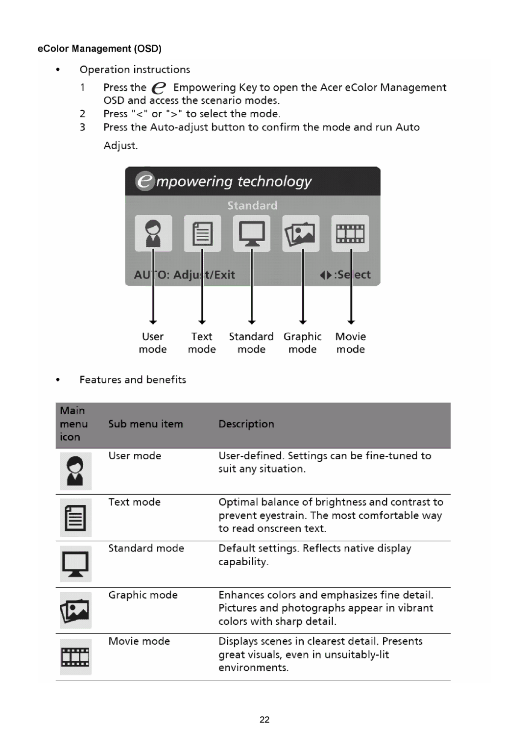
EColor Management OSD
Models:
B193R
1
22
48
48
Download
48 pages
17.27 Kb
19
20
21
22
23
24
25
26
Specs
Install
Chart of B193R
Symbol Description
Connector Information
Disassembly Procedure
Height Adjustment
Precautions
Using The Right Power Cord
Acer B193R Service Guide
Page 22
Image 22
eColor Management (OSD)
22
Page 21
Page 23
Page 22
Image 22
Page 21
Page 23
Contents
Acer B193R Service Guide
Service Guide Version and Revision
Version Release Date Revision History TPV model
Trademarks
Copyright
Disclaimer
Conventions
Preface
Precautions
Special Notes On LCD Monitors
Table Of Contents
Scope
Chart of B193R
Introduction
Description
Standard Test Conditions
Electrical Requirements
Measurement systems
LCD Monitor General Specification
TTL
General Specifications
LCD Panel Specification
Electrical Characteristics
Optical Specifications
Support Timing
Monitor Block Diagram
Main Board Diagram
Software Flow Chart
Remark
Symbol Description
Main Board Layout
Installation
Height Adjustment
Attaching/Removing The Base
Swivel
Tilt
Monitor Pivot
External Controls
Front panel controls
EColor Management OSD
How to Adjust a Setting
Adjusting the picture
Page
Using The Right Power Cord
Logo
Disassembly Procedure
Page
Page
No Power
Okng
No Picture LED is orange
Panel Power Circuit
OK NG
Key Board
Power Board No power
LED No Backlight
Connector Information
DVI Connector
Exploded Diagram Model B193R
Chapter
Part List
Picture Description
FFC Cable
Main Board
2007/05/08
170A8/90B8
Modify
Lvds Output
Power board
Feedback
Layout CN603
Key board
Top
Page
Image
Contents