G5900 specifications
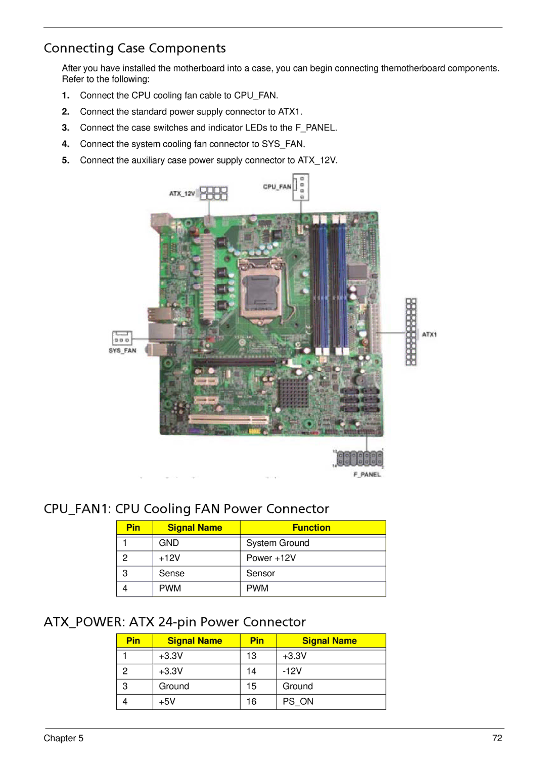
The Acer G5900 is a powerful and versatile desktop computer that has garnered attention for its performance and capability to cater to both casual users and gaming enthusiasts. Utilizing advanced technologies, the G5900 strikes a balance between efficiency and high-end specifications, making it a suitable choice for a variety of tasks.At the heart of the Acer G5900 is its robust processor. The device typically comes equipped with Intel or AMD processors, such as the Intel Core i5 or the AMD Ryzen series, ensuring quick processing speeds and reliable performance for multitasking and demanding applications. This processing power is essential for handling everything from everyday productivity tasks to more intensive gaming and content creation.
The G5900 is designed with ample memory options, often featuring configurations with up to 16GB of RAM. This is particularly beneficial for users who run multiple applications simultaneously, as it allows for smooth transitions and swift response times. The option to expand memory further adds to its longevity and adaptability, catering to evolving user needs over time.
Storage options on the Acer G5900 include both traditional HDDs and faster SSDs, with capacities ranging from 512GB to 2TB. This flexibility allows users to choose a setup that best fits their requirements, whether they prioritize speed or storage capacity. The inclusion of an SSD can significantly enhance boot times and application loading, elevating the overall user experience.
One of the standout features of the G5900 is its graphics capabilities. Depending on the configuration, it can be equipped with dedicated graphics cards from NVIDIA or AMD, making it apt for gaming enthusiasts and creative professionals alike. These graphics options enable the G5900 to handle modern titles and complex software with ease.
Connectivity is also a key aspect of the Acer G5900. The desktop generally comes with multiple USB ports, HDMI outputs, and sometimes even USB-C connectivity, providing ample options for connecting peripherals and external displays. Wireless options, including Wi-Fi and Bluetooth, enhance its versatility, allowing for seamless integration into modern home networks.
In terms of design, the Acer G5900 showcases a sleek and modern aesthetic, with a compact form factor that fits well in various environments. Its efficient cooling system is designed to maintain optimal performance even during heavy usage while ensuring quiet operation.
Overall, the Acer G5900 combines power, versatility, and modern design. With its cutting-edge specifications, ample storage, and graphics options, it stands out as an excellent choice for users looking to enhance their computing experience, whether for work, play, or everything in between.

