InterReach® In-building Coverage Solution
Typical Specifications
InterReach® In-building Coverage Solution
1900 PCS RF SPECIFICATIONS
Forward Path
System Bandwidth:
Frequency Range:
Output Power:
2X'sInput Level (at main hub): Gain:
Gain Variation:
OIP3:
CDMA ACPR1:
Spurious Output:
Reverse Path
System Bandwidth:
Frequency Range:
Gain:
Gain Variation:
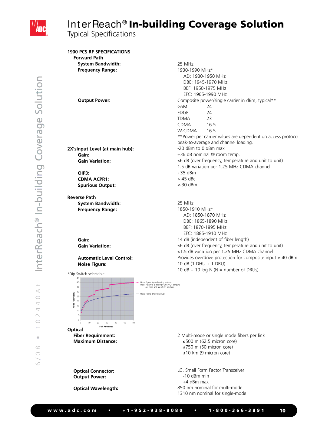
Automatic Level Control: Noise Figure:
*Dip Switch selectable
25 MHz
AD:
DBE:
BEF:
EFC:
Composite power/single carrier in dBm, typical**
GSM 24
EDGE 24
TDMA 23
CDMA 16.5
**Power per carrier values are dependent on access protocol
+36 dB nominal @ room temp.
≤6 dB (over frequency, temperature and unit to unit)
1.5dB variation per 1.25 MHz CDMA channel
+35 dBm
25 MHz
AD:
DBE:
BEF:
EFC:
14 dB (independent of fiber length)
≤6 dB (over frequency, temperature and unit to unit) <1.5 dB variation per 1.25 MHz CDMA channel
Provides overdrive protection for composite input
10 dB + 10 log N (N = number of DRUs)
0 2 4 4 0 A E
| 45 |
|
|
|
|
|
|
| 40 |
|
|
|
|
|
|
| 35 |
|
|
|
|
|
|
(dB) | 30 |
|
|
|
|
|
|
25 |
|
|
|
|
|
| |
Figure |
|
|
|
|
|
| |
20 |
|
|
|
|
|
| |
Noise | 15 |
|
|
|
|
|
|
|
|
|
|
|
|
| |
| 10 |
|
|
|
|
|
|
| 5 |
|
|
|
|
|
|
| 0 |
|
|
|
|
|
|
| 0 | 10 | 20 | 30 | 40 | 50 | 60 |
Noise Figure (typical analog system)
Note: Assumes 8 dB single unit NF, 4 outputs per host, and use of 2:1 splitters.
Noise Figure (Digivance ICS)
1
Optical
# of Antennas
6 / 0 8 •
Fiber Requirement: Maximum Distance:
Optical Connector: Output Power:
Optical Wavelength:
2
≤750 m (50 micron core) ≤10 km (9 micron core)
LC, Small Form Factor Transceiver
+4 dBm max
850 nm nominal for
1310 nm nominal for
w w w . a d c . c o m | • | + 1 - 9 5 2 - 9 3 8 - 8 0 8 0 | • | 1 - 8 0 0 - 3 6 6 - 3 8 9 1 | 10 |