RAID Mode Switches M2, M1, M0 (SW1:3 – SW1-5)
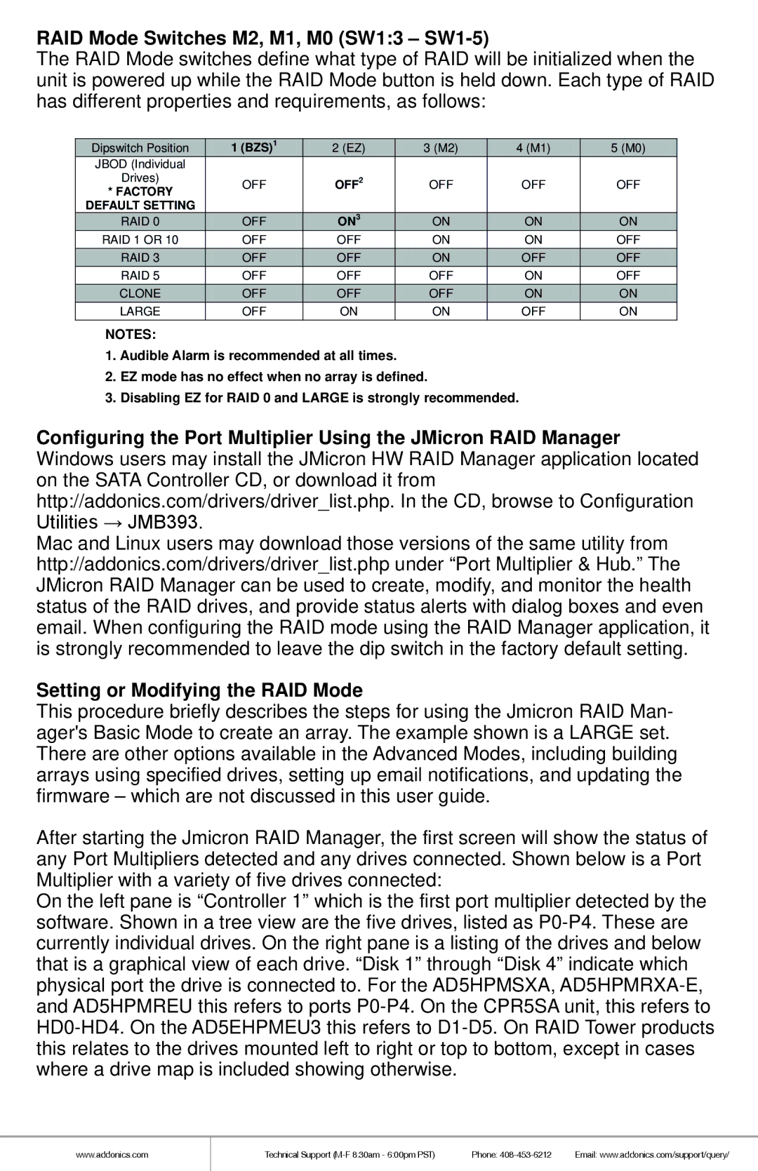
The RAID Mode switches define what type of RAID will be initialized when the unit is powered up while the RAID Mode button is held down. Each type of RAID has different properties and requirements, as follows:
| Dipswitch Position | 1 (BZS)1 |
| 2 (EZ) | 3 (M2) | 4 (M1) | 5 (M0) |
|
| ||||||
| JBOD (Individual |
|
|
|
|
|
|
| Drives) | OFF |
| OFF2 | OFF | OFF | OFF |
| * FACTORY |
|
|
|
|
|
|
| DEFAULT SETTING |
|
|
|
|
|
|
| RAID 0 | OFF |
| ON3 | ON | ON | ON |
| RAID 1 OR 10 | OFF |
| OFF | ON | ON | OFF |
| RAID 3 | OFF |
| OFF | ON | OFF | OFF |
| RAID 5 | OFF |
| OFF | OFF | ON | OFF |
| CLONE | OFF |
| OFF | OFF | ON | ON |
| LARGE | OFF |
| ON | ON | OFF | ON |
NOTES:
1.Audible Alarm is recommended at all times.
2.EZ mode has no effect when no array is defined.
3.Disabling EZ for RAID 0 and LARGE is strongly recommended.
Configuring the Port Multiplier Using the JMicron RAID Manager Windows users may install the JMicron HW RAID Manager application located on the SATA Controller CD, or download it from http://addonics.com/drivers/driver_list.php. In the CD, browse to Configuration Utilities → JMB393.
Mac and Linux users may download those versions of the same utility from http://addonics.com/drivers/driver_list.php under “Port Multiplier & Hub.” The JMicron RAID Manager can be used to create, modify, and monitor the health status of the RAID drives, and provide status alerts with dialog boxes and even email. When configuring the RAID mode using the RAID Manager application, it is strongly recommended to leave the dip switch in the factory default setting.
Setting or Modifying the RAID Mode
This procedure briefly describes the steps for using the Jmicron RAID Man- ager's Basic Mode to create an array. The example shown is a LARGE set. There are other options available in the Advanced Modes, including building arrays using specified drives, setting up email notifications, and updating the firmware – which are not discussed in this user guide.
After starting the Jmicron RAID Manager, the first screen will show the status of any Port Multipliers detected and any drives connected. Shown below is a Port Multiplier with a variety of five drives connected:
On the left pane is “Controller 1” which is the first port multiplier detected by the software. Shown in a tree view are the five drives, listed as
www.addonics.com
Technical Support | Phone: | Email: www.addonics.com/support/query/ |