Quick Start Guide
| For more detailed documentation, visit us online at www.adtran.com |
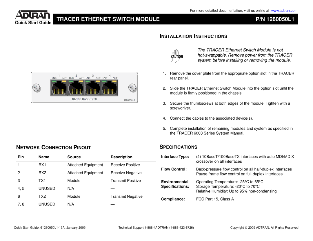
TRACER ETHERNET SWITCH MODULE | P/N 1280050L1 |
|
|
INSTALLATION INSTRUCTIONS
NETWORK CONNECTION PINOUT
Pin | Name | Source | Description |
|
|
|
|
1 | RX1 | Attached Equipment | Receive Positive |
2 | RX2 | Attached Equipment | Receive Negative |
3 | TX1 | Module | Transmit Positive |
4, 5 | UNUSED | N/A | — |
6 | TX2 | Module | Transmit Negative |
7, 8 | UNUSED | N/A | — |
The TRACER Ethernet Switch Module is not
1.Remove the cover plate from the appropriate option slot in the TRACER rear panel.
2.Slide the TRACER Ethernet Switch Module into the option slot until the module is firmly positioned in the chassis.
3.Secure the thumbscrews at both edges of the module. Tighten with a screwdriver.
4.Connect the cables to the associated device(s).
5.Complete installation of remaining modules and system as specified in the TRACER 6000 Series System Manual.
SPECIFICATIONS
Interface Type: (4) 10BaseT/100BaseTX interfaces with auto MDI/MDIX crossover on all interfaces
Flow Control:
Environmental Operating Temperature:
Specifications: Storage Temperature:
Compliance: FCC Part 15, Class A
Quick Start Guide, | Technical Support | Copyright © 2005 ADTRAN, All Rights Reserved |