TOTAL ACCESS 3010 50 - PIN TO 50 - PIN DSLAM CABLE ASSEMBLY | JOBAID |
| 0403 |
|
|
TOTAL ACCESS 3010
GENERAL
This Job Aid provides instructions for installation and operational use of the Total Access 3010 Backplane ADSL + POTS Converter Cable group (P/N 1182925L1).
DESCRIPTION
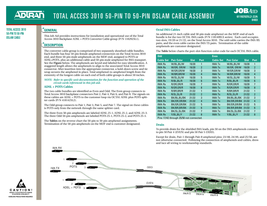
The converter cable group is comprised of two separately sheathed cable bundles. Each bundle has four
NOTE: Refer to specific unit documentation for the function and operation of the circuit cards referenced in this job aid.
ADSL + POTS Cables
The two cable bundles are identified as Even and Odd. The Even group connects to Total Access 3010 backplane connectors Pair 2, Pair 4, Pair 6, and Pair 8. The signals on these cables are ADSL + POTS to the customer loop via OCTAL ADSL plus POTS split- ter cards (P/N 4181425L2).
The Odd group connects to Pair 1, Pair 3, Pair 5, and Pair 7. The signal on these cables is POTS only from the network through the same splitter card.
The three Even
The Tables on the reverse chart the
Octal IMA Cables
An additional
The Table below charts the
Odd |
|
|
| Even |
|
|
|
Cable Set | Pair Color | Slot | Port | Cable Set | Pair Color | Slot | Port |
IMA Rx | W/BL,BL/W | 19/20 | 1 | IMA Tx | W/BL,BL/W | 19/20 | 1 |
IMA Rx | W/OR, OR/W | 19/20 | 2 | IMA Tx | W/OR, OR/W | 19/20 | 2 |
IMA Rx | W/GR,GR/W | 19/20 | 3 | IMA Tx | W/GR,GR/W | 19/20 | 3 |
IMA Rx | W/BR,BR/W | 19/20 | 4 | IMA Tx | W/BR,BR/W | 19/20 | 4 |
IMA Rx | W/SL,SL/W | 19/20 | 5 | IMA Tx | W/SL,SL/W | 19/20 | 5 |
IMA Rx | R/BL,BL/R | 19/20 | 6 | IMA Tx | R/BL,BL/R | 19/20 | 6 |
IMA Rx | R/OR,OR/R | 19/20 | 7 | IMA Tx | R/OR,OR/R | 19/20 | 7 |
IMA Rx | R/GR,GR/R | 19/20 | 8 | IMA Tx | R/GR,GR/R | 19/20 | 8 |
IMA Rx | R/BR,BR/R | 21/22 | 1 | IMA Tx | R/BR,BR/R | 21/22 | 1 |
IMA Rx | R/SL,SL/R | 21/22 | 2 | IMA Tx | R/SL,SL/R | 21/22 | 2 |
IMA Rx | BK/BL,BL/BK | 21/22 | 3 | IMA Tx | BK/BL,BL/BK | 21/22 | 3 |
IMA Rx | BK/OR,OR/BK | 21/22 | 4 | IMA Tx | BK/OR,OR/BK | 21/22 | 4 |
IMA Rx | BK/GR,GR/BK | 21/22 | 5 | IMA Tx | BK/GR,GR/BK | 21/22 | 5 |
IMA Rx | BK/BR,BR/BK | 21/22 | 6 | IMA Tx | BK/BR,BR/BK | 21/22 | 6 |
IMA Rx | BK/SL,SL/BK | 21/22 | 7 | IMA Tx | BK/SL,SL/BK | 21/22 | 7 |
IMA Rx | Y/BL,BL/Y | 21/22 | 8 | IMA Tx | Y/BL,BL/Y | 21/22 | 8 |
Pins 17/42 through 25/50 not connected.
Drain
To provide drain for the shielded IMA leads, pin 50 on the IMA amphenols connects to pin 50 Pair 4 (EVEN) and pin 50 Pair 5 (ODD).
Except for drain,
C A U T I O N !
SUBJECT TO ELECTROSTATIC DAMAGE
OR DECREASE IN RELIABILITY.
HANDLING PRECAUTIONS REQUIRED.
