TOTAL ACCESS 750 QUAD FXS/FXO
JOBAID
0006
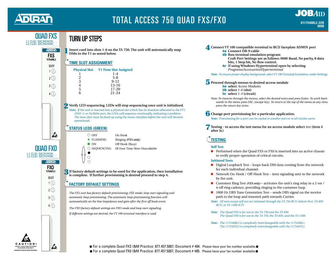
QUAD FXS
L1 CLEI: SIC2WXOK_ _
L2 CLEI: SIC2WXHK_ _
QUAD FXO
L1 CLEI: SIC2VXOK_ _
L2 CLEI: SIC2VXHK_ _
C A U T I O N !
TURN UP STEPS
1Insert card into slots
TIME SLOT ASSIGNMENT
Physical Slot | T1 Time Slot Assigned |
1 | |
2 | |
3 | |
4 | |
5 | |
6 |
2 Verify LED sequencing. LEDs will stop sequencing once unit is initialized.
Note: If the unit is inserted into a physical slot which has its timeslots allocated to the FT1
STATUS LEDS (GREEN)
● OFF | On Hook |
✸ FLASHING | Ringing (FXS only) |
● ON | Off Hook (Busy) |
● SEQUENCING | All Four Time Slots Unavailable |
● |
|
● |
|
● |
|
3If factory default settings to be used for the application, then installation is complete. If further provisioning is desired proceed to step 4.
FACTORY DEFAULT SETTINGS
The FXS unit has factory default provisioning: FXS mode, loop start signaling and automatic loop provisioning. The automatic loop provisioning function will automatically set the line impedance and gain after the first off hook event.
The FXO factory default settings are FXO mode and loop start signaling.
If different settings are desired, the VT 100 terminal interface is used.
4Connect VT 100 compatible terminal to BCU faceplate ADMIN port 4a Connect
4b Run terminal emulation program
Craft Port Settings are as follows: 9600 Baud, No parity, 8 data bits, 1 Stop bit, No flow control.
4c If using Windows Hyperteminal open by selecting Programs/Accessories/Hyperterminal
Note: To ensure proper display background, select VT 100 Terminal Emulation under Settings.
5 Proceed through menus to desired access module
5a select Access Modules
5b select
5c select
Note: To traverse through the menus, select the desired entry and press Enter. To work back- wards in the menu press ESC (escape key). To return to the top of the menu at any time, press the return key twice.
6 Change port provisioning for a particular application.
Note: Provisioning for a port can be copied to another port or to all similar ports.
7Testing - to access the test menu for an access module select test (item 4 after 5c)
TESTING
Self Test
■Performed when the Quad FXS or FX0 is inserted into an active chassis to verify proper operation of critical circuits.
Initiated Tests
■Digital Loopback Test – loops back DS0 data coming from the network for each individual channel.
■Network
■Customer Ring Test (FXS only) – activates the unit’s ring relay in a
■1000 Hz DRS Tone Generation Test – sends DRS signal on the receive path to the loop and transmit path towards Carrier.
Note: All tests except self test are initiated through the TA 750 BCU Admin Port, TA 850 RCU, or TA 1500 SCU.
Note: The Quad FXS is for use in the TA 750 and the TA 850.
The Quad FX0 is for use in the TA 750, the TA 850, and the TA 1500.
Note: The 1175408L2 is completely interchangeable with the 1175408L1. The 1175407L2 is completely interchangeable with the 1175407L1.
SUBJECT TO ELECTROSTATIC DAMAGE
OR DECREASE IN RELIABILITY.
HANDLING PRECAUTIONS REQUIRED.
■ For a complete Quad FXS I&M Practice: 877.457.5007, Document # 484. Please have your fax number available.■
■ For a complete Quad FX0 I&M Practice: 877.457.5007, Document # 485. Please have your fax number available.■