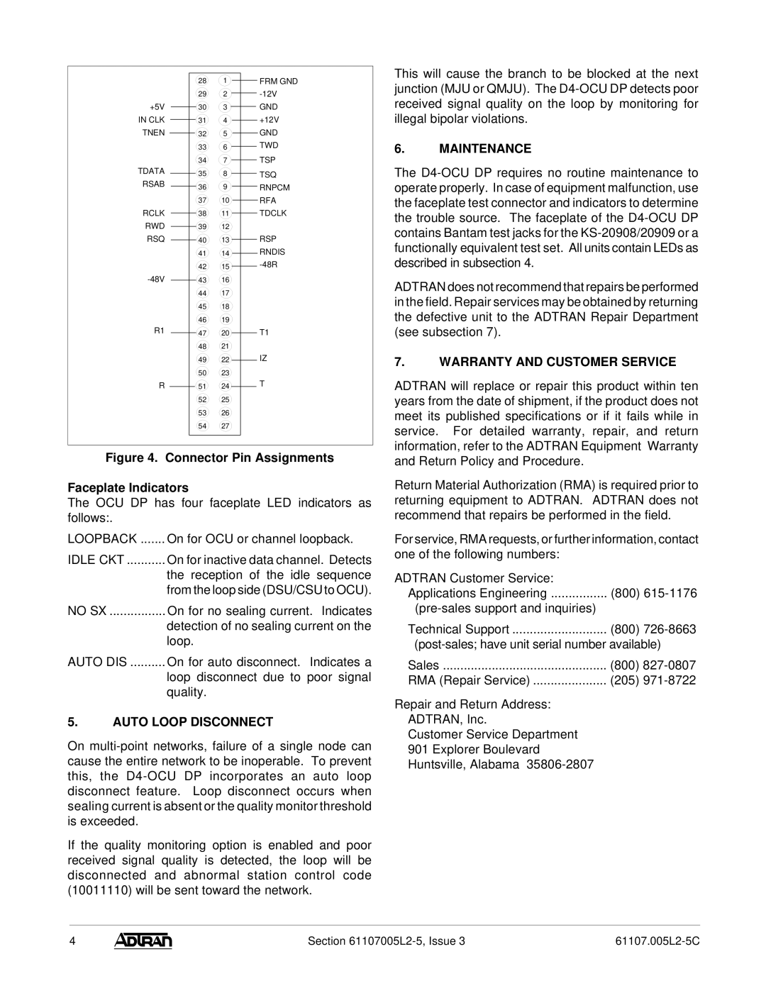
D4-OCU specifications
ADTRAN D4-OCU is a versatile and reliable digital access concentrator designed to efficiently manage and deliver telecommunication services. This device is primarily aimed at service providers looking to extend their network capabilities and enhance customer service by integrating robust functionalities into their infrastructure.One of the main features of the ADTRAN D4-OCU is its support for a wide range of digital signal formats, including DS1, DS3, and various T1/E1 standards. This flexibility allows service providers to accommodate different types of connections in a cohesive manner, making it easier to manage existing infrastructure while preparing for future upgrades. The device is engineered to provide a seamless transition between legacy TDM and modern packet-based networks, thereby facilitating a smooth migration path for operators.
The D4-OCU is built upon advanced technologies to optimize performance. It utilizes efficient signaling protocols that support both circuit-switched and packet-switched services. This dual capability ensures that service providers can meet the diverse needs of their customer base, whether they are providing traditional voice services or modern high-speed internet access. By supporting both voice and data traffic, the D4-OCU helps to maximize resource utilization, reducing operational costs and improving revenue potential.
Additionally, the ADTRAN D4-OCU features robust monitoring and management capabilities. With built-in diagnostic tools, service providers can easily track performance metrics, troubleshoot issues, and maintain service quality. This proactive approach to network management allows for quick resolutions to potential problems, ultimately enhancing customer satisfaction and reducing service disruptions.
Another key characteristic of the D4-OCU is its scalability. As demand for bandwidth increases, service providers can easily expand the capacity of the device by adding additional modules. This modular architecture ensures that as technology evolves and customer needs change, the D4-OCU can adapt accordingly without requiring a complete system overhaul.
In conclusion, the ADTRAN D4-OCU stands out as a powerful digital access concentrator that combines versatility, performance, and scalability. Its ability to support a wide range of digital signal formats, efficient integration of diverse technologies, and robust management features make it a valuable asset for telecommunications service providers. With the D4-OCU, operators can confidently navigate the complexities of modern networking while delivering high-quality services to their customers.

