JOBAID
HTU - C / 3192 | |
| 0104 |
|
|
HTU-C / 3192
CLEI: T1L4SNSC_ _
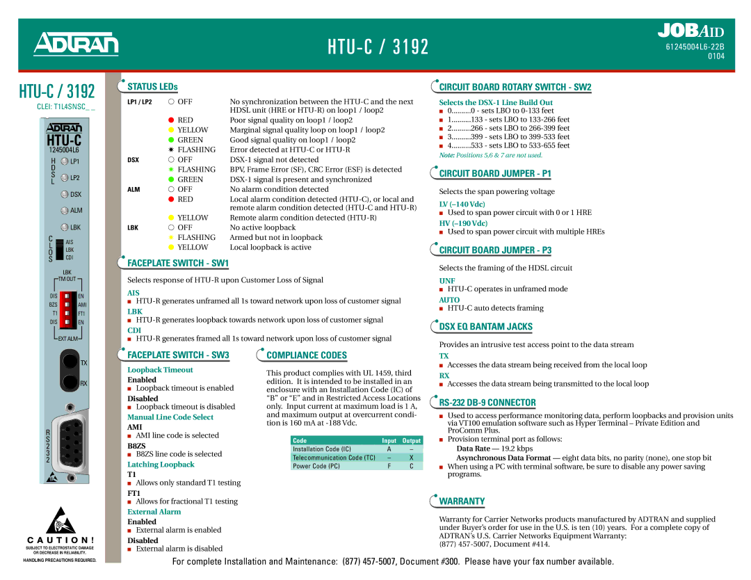
HTU-C
1245004L6
H ![]() LP1
LP1
D
S![]() LP2
LP2
L
![]() DSX
DSX
![]() ALM
ALM
LBK
C ![]() AIS
AIS
L
O LBK
S CDI
LBK
![]() TM OUT
TM OUT ![]()
DIS EN
BZS AMI
T1 FT1
DIS ![]() EN
EN
![]() EXT ALM
EXT ALM![]()
STATUS LEDs
LP1 / LP2 | ● OFF | No synchronization between the |
|
| HDSL unit (HRE or |
| ● RED | Poor signal quality on loop1 / loop2 |
| ● YELLOW | Marginal signal quality loop on loop1 / loop2 |
| ● GREEN | Good signal quality on loop1 / loop2 |
| ✷ FLASHING | Error detected at |
DSX | ● OFF | |
| ✷ FLASHING | BPV, Frame Error (SF), CRC Error (ESF) is detected |
| ● GREEN | |
ALM | ● OFF | No alarm condition detected |
| ● RED | Local alarm condition detected |
|
| remote alarm condition detected |
| ● YELLOW | Remote alarm condition detected |
LBK | ● OFF | No active loopback |
| ✷ FLASHING | Armed but not in loopback |
| ● YELLOW | Local loopback is active |
FACEPLATE SWITCH - SW1
Selects response of
AIS
■
LBK
■
CDI
■
CIRCUIT BOARD ROTARY SWITCH - SW2
Selects the DSX-1 Line Build Out
■0..........0 - sets LBO to
■1..........133 - sets LBO to
■2..........266 - sets LBO to
■3..........399 - sets LBO to
■4..........533 - sets LBO to
Note: Positions 5,6 & 7 are not used.
CIRCUIT BOARD JUMPER - P1
Selects the span powering voltage
LV
■Used to span power circuit with 0 or 1 HRE
HV
■Used to span power circuit with multiple HREs
CIRCUIT BOARD JUMPER - P3
Selects the framing of the HDSL circuit
UNF
■
AUTO
■
DSX EQ BANTAM JACKS
Provides an intrusive test access point to the data stream
![]() TX
TX
![]() RX
RX
R S 2 3 2
C A U T I O N !
SUBJECT TO ELECTROSTATIC DAMAGE
OR DECREASE IN RELIABILITY.
FACEPLATE SWITCH - SW3
Loopback Timeout
Enabled
■Loopback timeout is enabled
Disabled
■Loopback timeout is disabled
Manual Line Code Select
AMI
■AMI line code is selected
B8ZS
■B8ZS line code is selected
Latching Loopback
T1
■Allows only standard T1 testing
FT1
■Allows for fractional T1 testing
External Alarm
Enabled
■External alarm is enabled
Disabled
■External alarm is disabled
COMPLIANCE CODES
This product complies with UL 1459, third edition. It is intended to be installed in an enclosure with an Installation Code (IC) of “B” or “E” and in Restricted Access Locations only. Input current at maximum load is 1 A, and maximum output at overcurrent condi- tion is 160 mA at
Code | Input | Output |
Installation Code (IC) | A | – |
Telecommunication Code (TC) | – | X |
Power Code (PC) | F | C |
TX
■Accesses the data stream being received from the local loop
RX
■Accesses the data stream being transmitted to the local loop
RS-232 DB-9 CONNECTOR
■Used to access performance monitoring data, perform loopbacks and provision units via VT100 emulation software such as Hyper Terminal – Private Edition and ProComm Plus.
■Provision terminal port as follows:
Data Rate — 19.2 kbps
Asynchronous Data Format — eight data bits, no parity (none), one stop bit
■When using a PC with terminal software, be sure to disable any power saving programs.
WARRANTY
Warranty for Carrier Networks products manufactured by ADTRAN and supplied under Buyer’s order for use in the U.S. is ten (10) years. For a complete copy of ADTRAN’s U.S. Carrier Networks Equipment Warranty:
(877)
HANDLING PRECAUTIONS REQUIRED.
For complete Installation and Maintenance: (877)