| For more detailed documentation, visit us online at www.adtran.com |
NxT1 | P/N 1200346L2 |
|
|
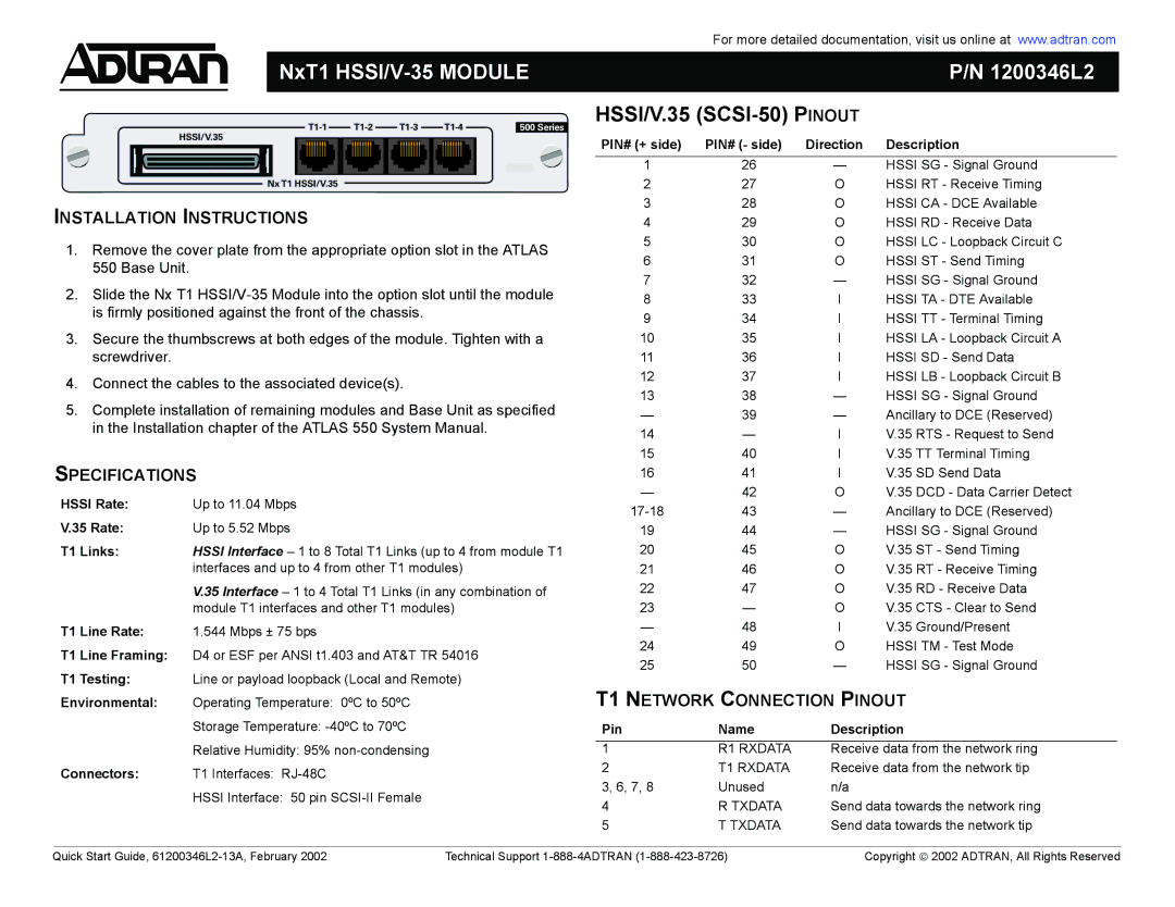
| HSSI/V.35 |
500 Series
|
| HSSI/V.35 | PIN# (+ side) | PIN# (- side) | Direction | Description | |
|
|
| |||||
|
|
| 1 | 26 | — | HSSI SG - Signal Ground | |
|
| Nx T1 HSSI/V.35 | 2 | 27 | O | HSSI RT - Receive Timing | |
INSTALLATION INSTRUCTIONS | 3 | 28 | O | HSSI CA - DCE Available | |||
4 | 29 | O | HSSI RD - Receive Data | ||||
1. Remove the cover plate from the appropriate option slot in the ATLAS | 5 | 30 | O | HSSI LC - Loopback Circuit C | |||
6 | 31 | O | HSSI ST - Send Timing | ||||
| 550 Base Unit. | ||||||
| 7 | 32 | — | HSSI SG - Signal Ground | |||
2. Slide the Nx T1 | |||||||
8 | 33 | I | HSSI TA - DTE Available | ||||
| is firmly positioned against the front of the chassis. | 9 | 34 | I | HSSI TT - Terminal Timing | ||
|
|
| |||||
3. Secure the thumbscrews at both edges of the module. Tighten with a | 10 | 35 | I | HSSI LA - Loopback Circuit A | |||
| screwdriver. |
| 11 | 36 | I | HSSI SD - Send Data | |
4. | Connect the cables to the associated device(s). | 12 | 37 | I | HSSI LB - Loopback Circuit B | ||
13 | 38 | — | HSSI SG - Signal Ground | ||||
5. Complete installation of remaining modules and Base Unit as specified | |||||||
— | 39 | — | Ancillary to DCE (Reserved) | ||||
| in the Installation chapter of the ATLAS 550 System Manual. | 14 | — | I | V.35 RTS - Request to Send | ||
|
|
| |||||
SPECIFICATIONS | 15 | 40 | I | V.35 TT Terminal Timing | |||
16 | 41 | I | V.35 SD Send Data | ||||
HSSI Rate: | Up to 11.04 Mbps | — | 42 | O | V.35 DCD - Data Carrier Detect | ||
43 | — | Ancillary to DCE (Reserved) | |||||
V.35 Rate: | Up to 5.52 Mbps | ||||||
19 | 44 | — | HSSI SG - Signal Ground | ||||
T1 Links: | HSSI Interface – 1 to 8 Total T1 Links (up to 4 from module T1 | 20 | 45 | O | V.35 ST - Send Timing | ||
|
| interfaces and up to 4 from other T1 modules) | 21 | 46 | O | V.35 RT - Receive Timing | |
|
| V.35 Interface – 1 to 4 Total T1 Links (in any combination of | 22 | 47 | O | V.35 RD - Receive Data | |
|
| module T1 interfaces and other T1 modules) | 23 | — | O | V.35 CTS - Clear to Send | |
T1 Line Rate: | 1.544 Mbps ± 75 bps | — | 48 | I | V.35 Ground/Present | ||
T1 Line Framing: | D4 or ESF per ANSI t1.403 and AT&T TR 54016 | 24 | 49 | O | HSSI TM - Test Mode | ||
25 | 50 | — | HSSI SG - Signal Ground | ||||
T1 Testing: | Line or payload loopback (Local and Remote) | ||||||
T1 NETWORK CONNECTION PINOUT | |||||||
Environmental: | Operating Temperature: 0ºC to 50ºC | ||||||
|
| Storage Temperature: | Pin | Name | Description | ||
|
| Relative Humidity: 95% | 1 | R1 RXDATA | Receive data from the network ring | ||
Connectors: | T1 Interfaces: | 2 | T1 RXDATA | Receive data from the network tip | |||
3, 6, 7, 8 | Unused | n/a |
| ||||
|
| HSSI Interface: 50 pin |
| ||||
|
| 4 | R TXDATA | Send data towards the network ring | |||
|
|
| |||||
|
|
| 5 | T TXDATA | Send data towards the network tip | ||
Quick Start Guide, | Technical Support | Copyright 2002 ADTRAN, All Rights Reserved |