TOTAL ACCESS OPTI - 3 CONTROLLER MODULE | JOBAID |
1550 NM | |
0401 | |
|
|
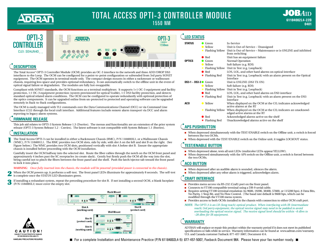
OPTI-3
CONTROLLER
CLEI: SOI4JN4D_ _
DESCRIPTION
STATUS OPTICS | DS3 | 1 | DS3 | DS3 | 3 | ACO |
| - | - |
| |||
OPTI-3
1184002L4
1550nm
APS TEST ACO
ENABLE
#61184002L4-22B#
LED STATUS
STATUS | ● Green | |
| ● Yellow | Unit is |
| ✷ Flashing Yellow | Unit is |
|
| from switching |
| ● Red | Unit has an equipment failure |
OPTICS | ● Green | Normal Operation |
| ● Yellow | Soft failure (e.g. RDI) |
| ✷ Flashing Yellow | Unit in Test (e.g. Loopback) |
The Total Access®
Compliant with SONET standards, the OCM functions as a terminal multiplexer. It supports 1+1
The OCM is easily managed with TL1 commands over the Data Communications Channel (DCC) or via Command Line Interface (CLI) through the local craft interface. Additional features include remote alarm transport via DCC and alarm reporting to legacy alarm systems.
FIRMWARE RELEASE
This job aid relates to
INSTALLATION
1 The Total Access
Carefully insert the OCM halfway into the selected slot. Route the fiber cables through the notch on the OCM front panel and approximately 4 inches past the SC receptacles (to create slack). Gently but firmly push the OCM all the way into the slot, being careful not to pinch the fibers between the front panel and the shelf. Push the latch/ejector tab toward the front panel to lock it into place.
WARNING: Once fully inserted into the chassis, the module will be powered (provided power is connected to the chassis).
2 When the OCM powers up, it performs a
3 If installing a redundant system, repeat the preceding procedure for slot B. If not installing a second OCM, a blank faceplate (P/N 1184005L1) must cover the empty slot.
C A U T I O N !
SUBJECT TO ELECTROSTATIC DAMAGE
OR DECREASE IN RELIABILITY.
| ● | Red | LOS, LOL, and other hard alarms on optical interface |
| ✷ Flashing Red | Unit in Test (e.g. Loopback) with an alarm present on the Optical | |
|
|
| Interface |
| Unit is ONLINE (DS3 TX ON) | ||
| ● Yellow | Soft failure (e.g. RDI) | |
| ✷ Flashing Yellow | Unit in Test (e.g. Loopback) | |
| ● Red | LOS, LOL, and other hard alarms on DS3 interface | |
| ✷ Flashing Red | Unit in Test (e.g. Loopback) with an alarm present on the DS3 | |
|
|
| Interface |
ACO | ● Yellow | When displayed on the OCM at the CO, indicates acknowledged | |
|
|
| active alarms at the RT |
| ✷ Flashing Yellow | When displayed on the OCM at the CO, indicates an unacknowl- | |
|
|
| edged active alarms at the RT |
| ● Red | Acknowledged alarms active on the shelf | |
| ✷ Flashing Red | Unacknowledged alarms active on the shelf | |
APS PUSHBUTTON
■When depressed simultaneously with the TEST/ENABLE switch on the Offline unit, a switch is forced between the two OCMs.
■When depressed with the TEST/ENABLE switch on the Online unit, it toggles LOCKOUT status.
TEST/ENABLE BUTTON
■When depressed alone, tests all unit LEDs (multicolor LEDs appear YELLOW).
■When depressed simultaneously with the APS switch on the Offline unit, a switch is forced between the two OCMs.
ACO BUTTON
■When depressed after an audible alarm is sounded, silences the alarm.
■When depressed after any other alarm is triggered, acknowledges alarm.
CRAFT INTERFACE
■Provides menu access via
■Connects to VT100 compatible terminal using a
■Requires setting VT100 terminal emulation (to 9600, 19200, 38400, 57600, or 115200 bps), 8 Data Bits, No Parity, 1 Stop Bit, and No Flow Control. (The baud rate default is 9600 bps, which can be modified through the VT100 menu system.
■Provides access to both OCMs installed in the chassis with connection to either OCM craft port.
NOTE: The
−28 dbm for IR equipment.
WARRANTY
ADTRAN will replace or repair this product within the warranty period if it does not meet its published specifications or fails while in service. Warranty information can be found at www.adtran.com/warranty. U.S. and Canada customer Faxback:
HANDLING PRECAUTIONS REQUIRED. | ■ For a complete Installation and Maintenance Practice (P/N |
|