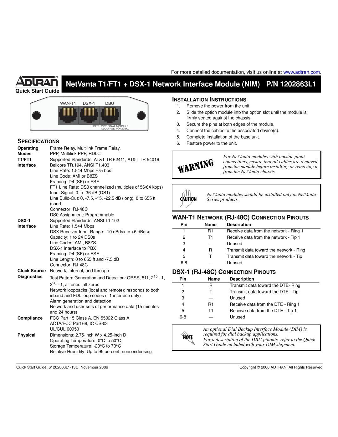
For more detailed documentation, visit us online at www.adtran.com.
®
NetVanta T1/FT1 +
Quick Start Guide
INSTALLATION INSTRUCTIONS
|
| DBU | 1. | Remove the power from the unit. | ||||||||||||
|
|
|
|
|
|
|
|
|
|
|
|
|
|
| ||
|
|
|
|
|
|
|
|
|
|
|
|
|
|
| ||
|
|
|
|
|
|
|
|
|
|
|
|
|
|
| 2. | Slide the option module into the option slot until the module is |
|
|
|
|
|
|
|
|
|
|
|
|
|
|
|
| firmly seated against the chassis. |
|
|
|
|
|
|
|
|
|
|
|
|
|
|
| 3. | Secure the pins at both edges of the module. |
|
|
|
|
|
|
|
|
|
|
|
|
|
|
| ||
|
|
|
|
|
|
|
|
|
|
|
|
|
|
| 4. | Connect the cables to the associated device(s). |
|
|
|
|
|
|
|
|
|
|
|
|
|
|
| ||
SPECIFICATIONS |
|
|
| 5. | Complete installation of the base unit. | |||||||||||
|
|
| 6. | Restore power to the unit. | ||||||||||||
Operating | Frame Relay, Multilink Frame Relay, |
|
|
|
| |
Modes | PPP, Multilink PPP, HDLC |
|
| For NetVanta modules with outside plant | ||
T1/FT1 | Supported Standards: AT&T TR 62411, AT&T TR 54016, |
|
| |||
|
| connections, ensure that all cables are removed | ||||
Interface | Bellcore TR.194, ANSI T1.403 |
|
| from the module before installing or removing it | ||
| Line Rate: 1.544 Mbps ±75 bps |
|
| from the NetVanta chassis. | ||
| Line Code: AMI or B8ZS |
|
|
|
| |
| Framing: D4 (SF) or ESF |
|
|
|
| |
| FT1 Line Rate: DS0 channelized (multiples of 56/64 kbps) |
|
|
|
| |
| Input Signal: 0 to |
| NetVanta modules should be installed only in NetVanta | |||
| Line |
| Series products. | |||
|
| |||||
| (short) |
|
|
|
| |
| Connector: |
|
|
|
| |
| DS0 Assignment: Programmable |
| ||||
Supported Standards: ANSI T1.102 | ||||||
Pin | Name | Description | ||||
Interface | Line Rate: 1.544 Mbps | |||||
|
|
|
| |||
| DSX Receiver Input Range: | 1 | R1 | Receive data from the network - Ring 1 | ||
| Capacity: 1 to 24 DS0s | 2 | T1 | Receive data from the network - Tip 1 | ||
| Line Codes: AMI, B8ZS | 3 | — | Unused | ||
| 4 | R | Transmit data toward the network - Ring | |||
| Framing: D4 (SF) or ESF | |||||
| 5 | T | Transmit data toward the network - Tip | |||
| Line Length: 0 to 655 ft and | |||||
| — | Unused | ||||
| Connector: | |||||
|
|
|
|
| ||
Clock Source | Network, internal, and through |
| ||||
Diagnostics | Test Pattern Generation and Detection: QRSS, 511, 215 - 1, | Pin | Name | Description | ||
| 220 - 1, all ones, all zeros |
|
|
|
| |
| 1 | R | Transmit data toward the DTE- Ring | |||
| Network loopbacks (local and remote); responds to both | 2 | T | Transmit data toward the DTE - Tip | ||
| inband and FDL loop codes (T1 interface only) | |||||
| 3 | — | Unused | |||
| Alarm generation and detection | |||||
| 4 | R1 | Receive data from the DTE - Ring 1 | |||
| Network and user sets of performance data (15 minutes | |||||
| 5 | T1 | Receive data from the DTE - Tip 1 | |||
| and 24 hours) | |||||
| — | Unused | ||||
Compliance | FCC Part 15 Class A, EN 55022 Class A | |||||
| ACTA/FCC Part 68, IC |
|
|
|
| |
| UL/CUL 60950 |
| An optional Dial Backup Interface Module (DIM) is | |||
Physical | Dimensions: |
| required for dial backup applications. | |||
| Operating Temperature: 0°C to 50°C |
| For a description of the DBU pinouts, refer to the Quick | |||
| Storage Temperature: |
| Start Guide included with your DIM shipment. | |||
| Relative Humidity: Up to 95 percent, noncondensing |
|
|
|
| |
|
|
|
|
| ||
Quick Start Guide, | Copyright © 2006 ADTRAN, All Rights Reserved |
