8472B specifications
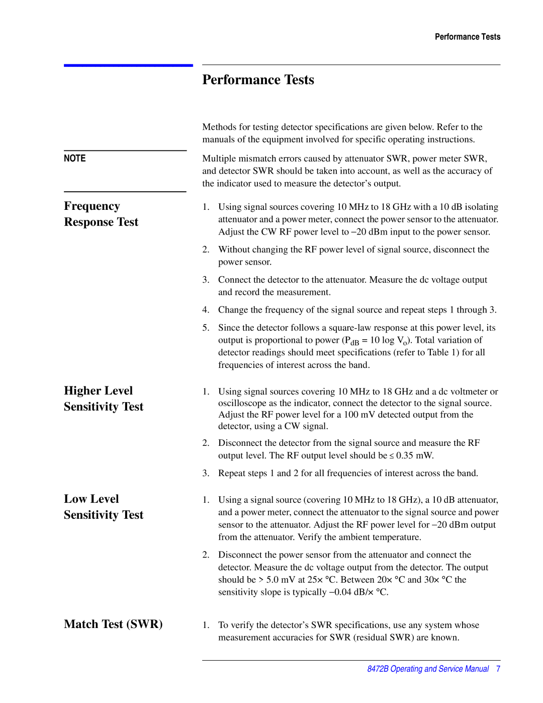
Agilent Technologies 8472B is a high-performance microwave amplifier that has earned a reputation for reliability and precision in various applications including telecommunications, signal testing, and RF research. As a compact and versatile device, the 8472B combines cutting-edge technology with user-friendly functionality, making it a staple in many laboratories and test environments.One of the standout features of the 8472B is its impressive frequency range. It operates effectively from 10 MHz to 20 GHz, which accommodates a wide array of microwave testing scenarios. This range ensures that it can handle both low and high-frequency signals, making it suitable for various applications, including wireless communication systems and radar testing.
The amplifier offers a nominal gain of 20 dB, with the ability to provide consistent performance across its frequency spectrum. This high gain factor is essential for amplifying weak signals without introducing significant noise, thus enhancing the quality of the transmitted signals. Additionally, the 8472B features a low noise figure, typically around 4 dB, which is crucial for maintaining signal integrity during amplification.
Another significant characteristic of the 8472B is its robust design, which includes overvoltage protection features. This makes the device resilient to unexpected voltage spikes, ensuring longevity and stability in diverse operating conditions. The amplifier also has a wide dynamic range, allowing it to perform well under varying signal conditions.
With respect to connectivity, the Agilent Technologies 8472B typically features 50-ohm connectors, which are standard in RF applications. Its compact form factor allows for easy integration into existing test setups, whether in a bench environment or within a larger instrumentation rack.
User-friendly features like an easily accessible control panel and clear indicators provide straightforward operation, facilitating quick adjustments and real-time monitoring. The 8472B also supports a variety of power supply configurations, giving users flexibility in incorporating it into their setups.
In conclusion, the Agilent Technologies 8472B microwave amplifier embodies the ideal blend of performance, durability, and versatility. Its frequency range, gain capabilities, low noise figure, and robust design make it an exceptional choice for engineers and researchers dealing with RF and microwave applications, cementing its status as a critical tool in the field.

