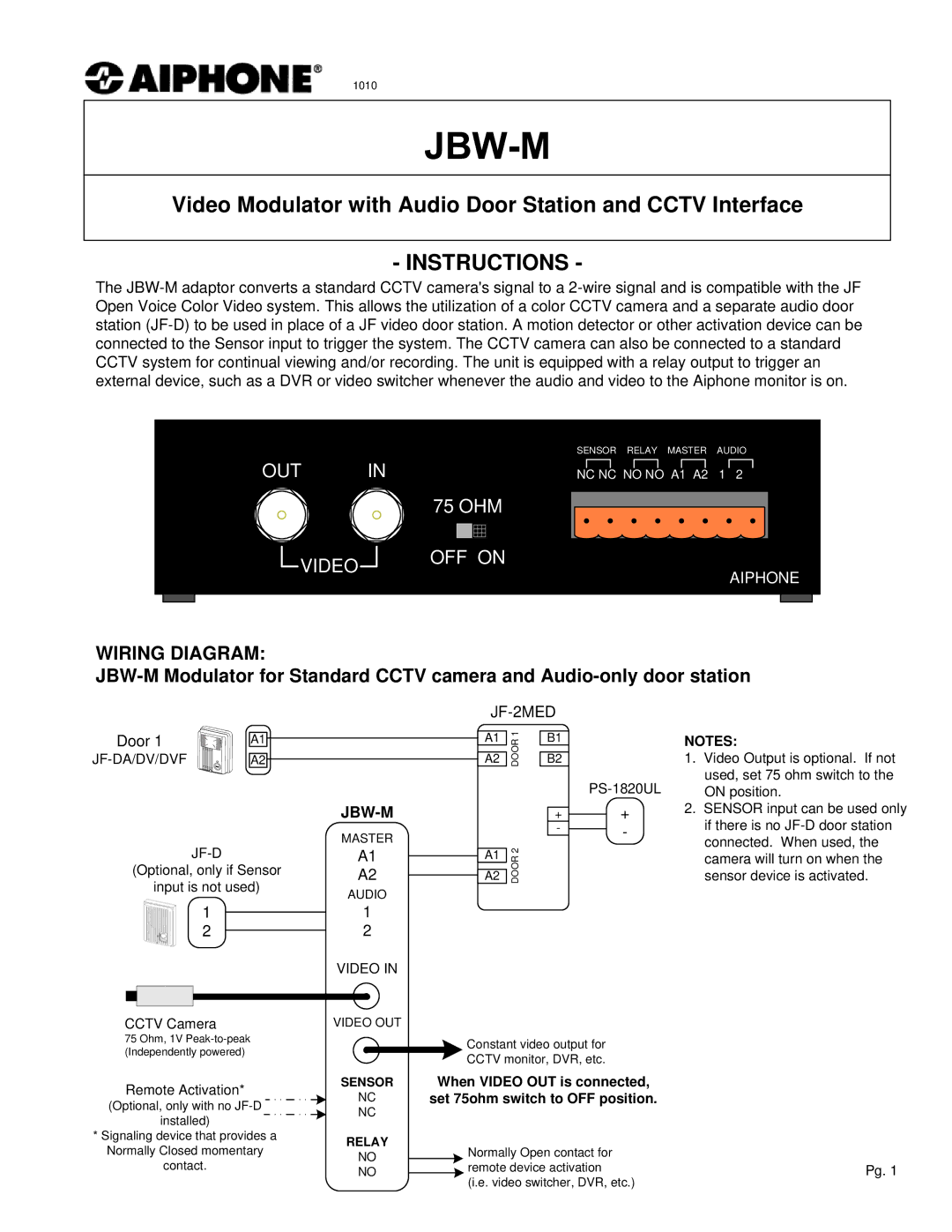
JBW-M specifications
The Aiphone JBW-M is an advanced intercom system designed to enhance communication across various settings, from residential buildings to commercial properties. Renowned for its innovative features and user-friendly design, the JBW-M ensures clear communication and improved security for users.One of the standout features of the JBW-M is its high-resolution color screen. With a vibrant display, users can easily see who is at the door, enhancing safety and convenience. The screen's clarity allows for detailed visuals, making it easier to identify visitors or delivery personnel at a glance. The unit also offers a user-friendly interface, with intuitive controls that enable quick access to various functions.
The JBW-M utilizes advanced audio technology for crystal-clear sound. Its built-in speakers and microphones are engineered to minimize background noise, ensuring that conversations are clear and intelligible. This audio clarity is crucial for effective communication, particularly in busy environments where distractions are common.
With its robust construction, the JBW-M is built to withstand various weather conditions, making it suitable for outdoor installation. The unit's durability ensures long-term performance, even when exposed to harsh elements. Additionally, the JBW-M features temperature resistance, allowing it to function effectively in both hot and cold climates.
Security is a top priority for the JBW-M, which is why it includes features such as video recording capabilities and motion detection. The system can capture video footage when motion is detected, providing peace of mind for homeowners and business operators. This function can be particularly useful for monitoring activity around entry points, enhancing overall security.
Connectivity is another significant aspect of the JBW-M. The intercom system can be easily integrated with other security systems, including cameras and alarms, to create a comprehensive security solution. This connectivity allows users to manage their security settings from a single interface, streamlining operations and improving efficiency.
In conclusion, the Aiphone JBW-M intercom system is a sophisticated solution that combines modern technology with user-friendly features. Its high-resolution display, superior audio quality, durability, and security capabilities make it an excellent choice for anyone seeking to enhance communication and safety. The JBW-M stands out as a reliable and effective intercom system in today’s marketplace, catering to both residential and commercial needs.

