Specia l
Ord e r
Prod u c t s
LDF
LDF Loudspeaker Master Station with External Control Capability
LDF-20C LDF-40C
LDF-20CA LDF-40CA
- LDF SUPPLEMENT TO LAF-C/CA INSTRUCTIONS -
The LDF Loudspeaker Intercom and External Control System is designed for communication between a central master station and remote intercom stations. The LDF is an expanded feature version of the
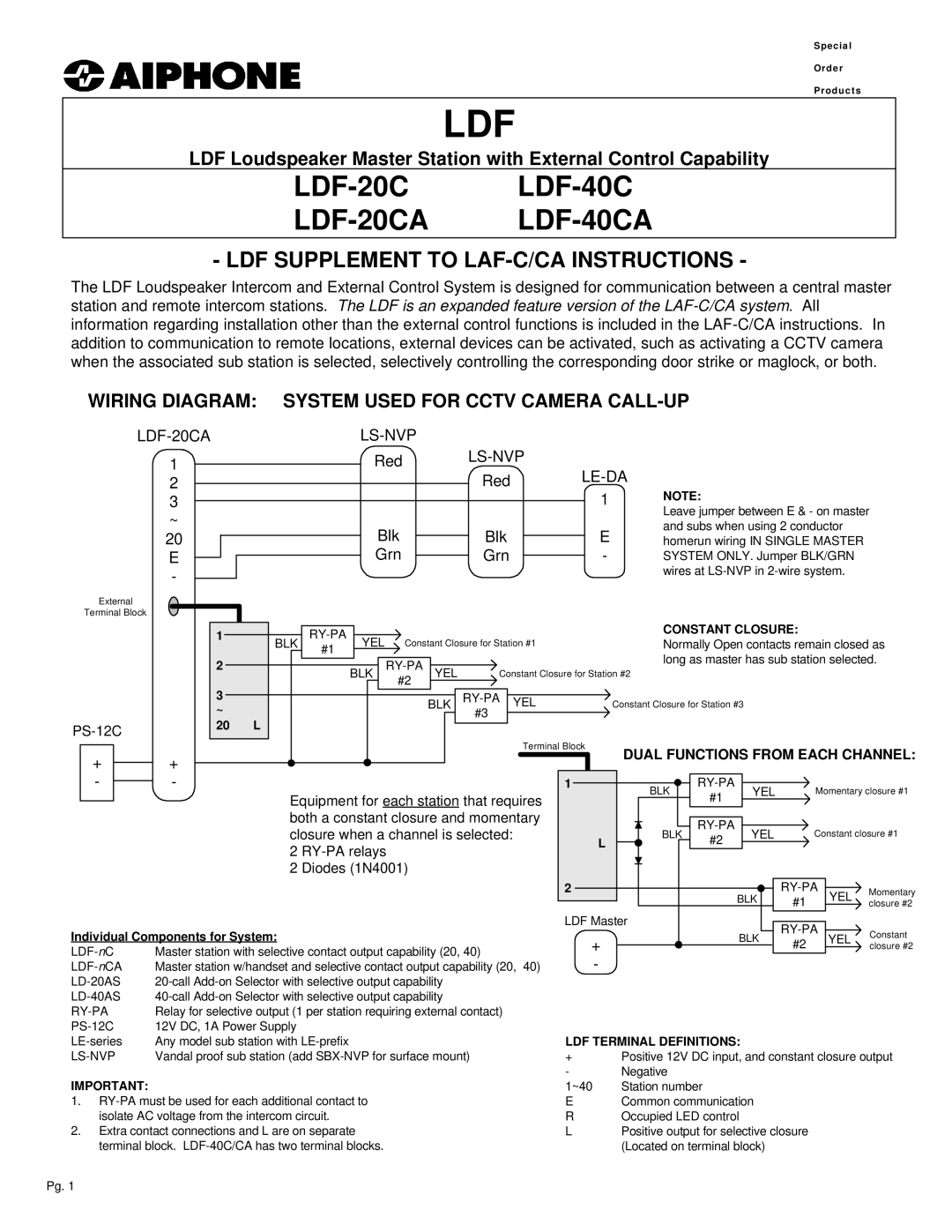
WIRING DIAGRAM: SYSTEM USED FOR CCTV CAMERA CALL-UP
LDF-20CA
1
2
3
~
20
E
-
External
Terminal Block
|
|
|
Red |
|
|
| Red | |
|
| 1 |
Blk | Blk | E |
Grn | Grn | - |
NOTE:
Leave jumper between E & - on master and subs when using 2 conductor homerun wiring IN SINGLE MASTER SYSTEM ONLY. Jumper BLK/GRN wires at
1 |
|
|
|
|
|
|
|
|
|
|
| CONSTANT CLOSURE: | |
| BLK |
| YEL |
| Constant Closure for Station #1 | Normally Open contacts remain closed as | |||||||
|
| #1 |
|
| |||||||||
2 |
|
|
|
|
|
|
|
|
|
|
| long as master has sub station selected. | |
|
|
|
|
|
|
|
|
|
| ||||
|
|
|
| BLK |
| YEL | Constant Closure for Station #2 |
| |||||
|
|
|
|
|
|
|
|
| #2 |
|
|
| |
|
|
|
|
|
|
|
|
|
|
|
| ||
| 3 | BLK | YEL |
| Constant Closure for Station #3 |
|
|
|
| |||
| ~ |
|
|
|
|
| ||||||
|
| #3 |
|
|
|
|
|
|
|
|
| |
20 | L |
|
|
|
|
|
|
|
|
|
| |
|
|
|
|
|
|
|
|
|
|
|
| |
|
|
|
|
| Terminal Block | DUAL FUNCTIONS FROM EACH CHANNEL: | ||||||
+ | + |
|
|
|
|
| ||||||
|
|
|
|
|
|
|
|
|
|
| ||
- | - |
|
|
|
| 1 | BLK | YEL |
| Momentary closure #1 | ||
|
| Equipment for each station that requires |
| #1 |
| |||||||
|
|
|
|
|
|
|
| |||||
|
| both a constant closure and momentary |
|
|
|
|
|
| ||||
|
| closure when a channel is selected: |
|
|
| BLK | YEL |
| Constant closure #1 | |||
|
|
|
| L | #2 |
| ||||||
|
| 2 |
|
|
|
|
|
|
|
| ||
|
|
|
|
|
|
|
|
|
|
|
| |
|
| 2 Diodes (1N4001) |
|
|
|
|
|
|
|
|
|
|
|
|
|
|
|
| 2 |
|
|
| Momentary | ||
|
|
|
|
|
|
|
| BLK | #1 | YEL | closure #2 | |
|
|
|
|
|
| LDF Master |
|
|
| |||
Individual Components for System: |
|
|
|
|
| BLK | Constant | |||||
|
|
| + |
| #2 | YEL | ||||||
|
|
|
| closure #2 | ||||||||
Master station with selective contact output capability (20, 40) |
|
|
|
|
|
| ||||||
|
| - |
|
|
|
|
|
| ||||
Master station w/handset and selective contact output capability (20, | 40) |
|
|
|
|
|
| |||||
|
|
|
|
|
|
|
|
|
| |||
|
|
|
|
|
|
|
|
|
| |||
Relay for selective output (1 per station requiring external contact) |
|
|
|
|
|
|
|
|
| |||
12V DC, 1A Power Supply |
|
|
|
|
|
|
|
|
|
| ||
Any model sub station with |
|
|
| LDF TERMINAL DEFINITIONS: |
|
|
|
| ||||
| Vandal proof sub station (add |
|
| + | Positive 12V DC input, and constant closure output | |||||||
|
|
|
|
|
| - | Negative |
|
|
|
|
|
IMPORTANT: |
|
|
|
|
| 1~40 | Station number |
|
|
|
| |
1. |
|
|
| E | Common communication |
|
|
| ||||
isolate AC voltage from the intercom circuit. |
|
|
| R | Occupied LED control |
|
|
|
| |||
2. Extra contact connections and L are on separate |
|
|
| L | Positive output for selective closure |
|
| |||||
terminal block. |
|
|
|
| (Located on terminal block) |
|
|
| ||||
Pg. 1