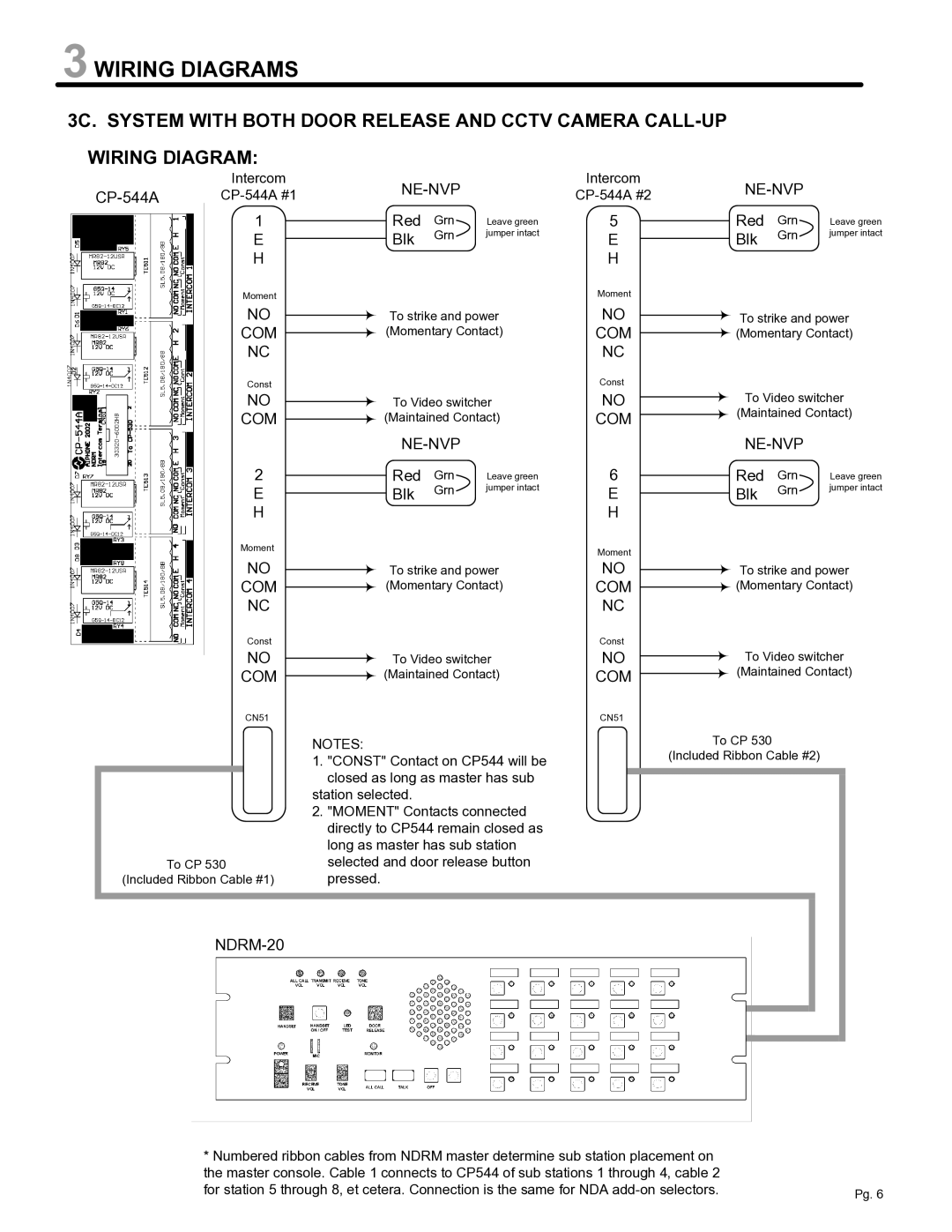
NDRM specifications
The Aiphone NDRM is an innovative intercom and door access solution that embodies the latest in communication technology, ensuring both security and convenience for residential and commercial applications. With its sleek design and user-friendly interface, the NDRM is both functional and aesthetically pleasing, making it an ideal choice for modern properties.One of the main features of the Aiphone NDRM is its high-resolution video capability. Equipped with a state-of-the-art camera, the NDRM captures clear images and videos, allowing users to see who is at the door before granting access. This feature enhances security and provides peace of mind, especially for those living in busy urban areas or neighborhoods with higher crime rates.
Another significant characteristic of the NDRM is its two-way audio communication. Users can engage in direct conversations with visitors via the intercom system, which is complemented by a high-quality microphone and speaker setup. This feature not only facilitates seamless communication but also allows for quick decision-making regarding granting or denying access.
The NDRM integrates robust connectivity options, supporting both wired and wireless configurations. This flexibility is crucial for adapting to different installation environments and ensuring reliable communications. Moreover, the system can be integrated with various smartphones and tablets through specialized applications, allowing homeowners to monitor their door and communicate with visitors even when they are away from home.
In terms of technology, the Aiphone NDRM utilizes advanced encryption protocols to safeguard communication, ensuring that conversations and video feeds remain secure from potential hackers. Additionally, the system is designed to seamlessly integrate with various home automation systems, allowing users to incorporate it into their broader security framework effortlessly.
Characteristically, the NDRM is designed for durability and efficiency. The housing is weather-resistant, ensuring that the device can withstand various environmental conditions. Furthermore, its energy-efficient operation helps minimize power consumption while maintaining maximum functionality.
Overall, the Aiphone NDRM represents a significant advancement in intercom technology, combining high-quality video, reliable audio communication, robust security features, and innovative connectivity options. It provides a comprehensive solution for property owners aiming to enhance their security while ensuring ease of access and communication. Whether for residential or commercial use, the NDRM stands out as a leader in the intercom industry, offering reliability and cutting-edge technology that meets the demands of today's consumers.

