Special
Order
Products
VC-MW/B
Dual Entrance Adaptor for VC-M
- INSTRUCTIONS -
The
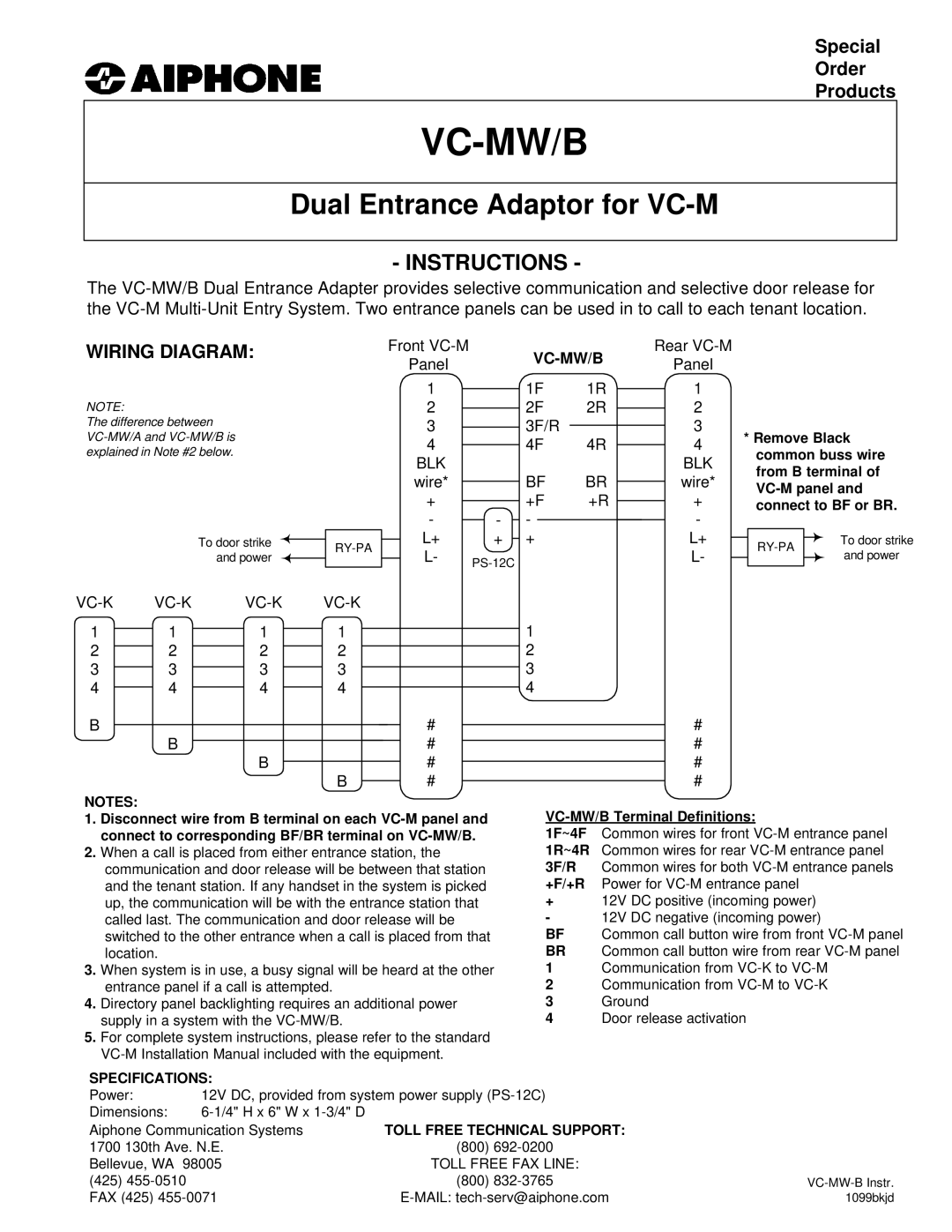
WIRING DIAGRAM:
NOTE:
The difference between
To door strike and power
Front |
|
|
| Rear | |||
Panel |
|
|
| Panel | |||
|
|
|
|
| |||
| 1 |
| 1F | 1R | 1 | ||
2 |
| 2F | 2R |
| 2 | ||
3 |
|
| 3F/R |
| 3 | ||
4 |
| 4F | 4R |
| 4 | ||
BLK |
|
|
|
|
| BLK | |
wire* |
| BF | BR |
| wire* | ||
+ |
| +F | +R |
| + | ||
- | - | - |
|
|
| - | |
| L+ | + | + |
|
| L+ | |
|
| ||||||
| L- |
|
|
|
| L- | |
|
|
|
|
|
|
| |
*Remove Black common buss wire from B terminal of
|
| To door strike | |
| |||
|
| and power | |
|
|
| |
|
|
| |
|
|
|
|
1 | 1 | 1 | 1 |
| 1 |
2 |
|
|
|
| 2 |
2 | 2 | 2 |
| ||
3 | 3 | 3 | 3 |
| 3 |
4 | 4 | 4 | 4 |
| 4 |
B | # | # |
B | # | # |
B | # | # |
B | # | # |
NOTES:
1.Disconnect wire from B terminal on each
2.When a call is placed from either entrance station, the communication and door release will be between that station and the tenant station. If any handset in the system is picked up, the communication will be with the entrance station that called last. The communication and door release will be switched to the other entrance when a call is placed from that location.
3.When system is in use, a busy signal will be heard at the other entrance panel if a call is attempted.
4.Directory panel backlighting requires an additional power supply in a system with the
5.For complete system instructions, please refer to the standard
VC-MW/B Terminal Definitions:
1F~4F Common wires for front
+12V DC positive (incoming power)
- 12V DC negative (incoming power)
BF Common call button wire from front
BR Common call button wire from rear
1 Communication from
2 Communication from
3Ground
4Door release activation
SPECIFICATIONS: |
| |
Power: | 12V DC, provided from system power supply | |
Dimensions: |
| |
Aiphone Communication Systems | TOLL FREE TECHNICAL SUPPORT: | |
1700 130th Ave. N.E. | (800) | |
Bellevue, WA 98005 | TOLL FREE FAX LINE: | |
(425) |
| (800) |
FAX (425) | ||