4.Fijar la Mordaza de Cable restante como se indica en la parte 2. Hay que recortar el exceso de cabo de manera que sólo queden de 1 a 2 pulgadas después de la Mordaza
5.Revisar el Ensamblado para cerciorarse de que la Paleta esté libre de toda obstrucción.
ATENCIÓN: EL USO DEL CABLE DE APOYO SECUNDARIO NO GARANTIZA LA PROTECCIÓN DE PERSONAS CONTRA LESIONES Y EL MONTAJE DEL VENTILADOR Y DEL CABLE PODRÍAN DAÑARSE SI SE MALTRATAN, SE DESCUIDAN O NO SE INSTALAN BIEN.
8
hojas conectado ampropiadamente a tierra. |
2. Utilizando el cordón accionador, seleccione la velocidad deseada del Ventilador. |
3. ADVERTENCIA: Este ventilador debe ser usa do solmente en unambiente |
limpio y seco. Si producto esta montado de alguna otra manera espec´ifica |
que indica la hoja de instrucción, purdiera anularse y no tener valor la |
garantia del fabricante. |
MANTENIMIENTO
ADVERTENCIA: DESCONECTE SIEMPRE EL CORDÓN ANTES DE INTENTAR REALIZAR CUALQUIER FUNCIÓN DE SERVICIO.
LIMPIEZA: Use un trapo y una solución de jabón suave, tal como detergente líquido para lavar trastes.
ADVERTENCIA: No use gasolina, bencina, diluyente de pintura ni limpiadores fuertes en aerosol, ya que éstos dañarán el ventilador.
ALMACENAMIENTO: Cuando no lo utilice, mantenga el aparato en un lugar limpio y seco.
EL MOTOR HA SIDO PERMANENTEMENTE LUBRICADO.
| | Ref | NO. DE PARTE | DESCRIPCIÓN | CANT. |
| | No. |
| | | | | | |
1 | 02030112A | | Motor Asamblea | | 1 |
2 | 05060015 | | Placa de Pivote | | 2 |
3 | 2091162 | | Tornillo de #8 x 1/2 PPH Tipo F | | 4 |
4 | 5097090BK | | Rejilla Trasera | | 1 |
5 | 5090045 | | Tornillo de #10-32 x 1/2" | | 3 |
| | | | | | |
6 | 5082080CH | | Hélice | | 1 |
7 | 5090044 | | Tornillo Prisionero de 1/4-28 x 3/8 | | 1 |
8 | 2091158 | | Remache | | 2 |
9 | 05060031 | | Horqueta | | 1 |
| 10 | 02011601 | | Espaciador de Caucho | | 2 |
11 | 5097080BK | | Rejilla Delantera | | 1 |
12 | 2091143 | | Tornillo de #8 x 3/8" PPH Type F | | 4 |
13 | 02084613 | | Ojo de Buey | | 1 |
14 | ** | | Grapa de Cable | | 2 |
15 | ** | | Cable de Seguridad | | 1 |
| | | | | | |
| 16 | ** | | El Cordón | | 1 |
** Suministros por Bolso de Piezas Componentes Físicas (02098012)
| | H | VEL | OC | |
| G | | IT | |
H | I | | | Y |
| | | | |
| | | | | R |
I | | | | R |
A | | | | |
| R | C | C | TO | |
| | A | |
| | | IR UL | |
DESCRIPTION
The AirKing 14" (35.5 cm) Multi Mount Fan features Pull Cord opera- tion and a 3-paddle Fan Blade. This Fan has a permanently lubricated motor with a 9 ft. (2.74 m) 18/3 cord set and is constructed of sturdy, powder coated steel.
SPECIFICATIONS
Motor | 120 V, 50/60 Hz (14", 35.5 cm) |
Blade diameter | 14" (35.5 cm) Model 1VN45/9314 |
Speeds | 3 | | | | |
Control | Pull Cord | | |
Air flow distribution | 360° | | | | |
Approvals | UL Listed. Close mesh Fan guard |
| | meets OSHA requirements. |
| | | | | | |
| MODEL | 1VN45A/9314A | | |
| SPEED | HIGH | MED | | LOW | |
| | | | | | |
| CFM | 1650 | 1470 | | 1180 | |
| | | | | | |
| M3/s | 0.78 | 0.69 | | 0.56 | |
| RPM | 1498 | 1296 | | 934 | |
| | | | | | |
| Amps | 0.58 | 0.50 | | 0.44 | |
| Watts | 63 | 56 | | 48 | |
| dB A | 58 | 55 | | 48 | |
GENERAL SAFETY INFORMATION
1.Make certain that the power source conforms to the electrical require- ments of the Fan.
2.The power cord is equipped with a three-prong grounded plug that must be inserted into a matching receptacle. Under no circumstances must the grounding prong be cut off the plug. Where a two-prong wall receptacle is encountered, it must be replaced with a properly grounded three-prong receptacle installed in accordance with the National Electrical Code (NEC) and all applicable local codes and ordinances. This work must be done only by a qualified electrician, using copper wire only.
WARNING: USE OF A THREE-PRONG TO TWO-PRONG ADAPTER IS NOT RECOMMENDED. IMPROPER CONNECTION MAY CREATE THE RISK OF ELECTROCUTION. USE OF SUCH ADAPTERS IS NOT PERMITTED IN CANADA.
3.Where possible, avoid the use of extension cords. If they must be used, minimize the risk of overheating by ensuring that they are UL listed and of the proper gage and length. Never use a single extension cord to operate more than one Fan.
4.Do not insert fingers or foreign objects into the Fan. Do not block or tamper with the Fan in any manner while it is in operation. Do not touch the Fan while in operation or just after it has been turned off, as some parts may be hot enough to cause injury.
5.Unplug power cord before installing or servicing the Fan.
WARNING: DO NOT DEPEND UPON THE ON-OFF SWITCH AS THE SOLE MEANS OF DISCONNECTING POWER WHEN INSTALLING OR SERVICING THE FAN. ALWAYS UNPLUG THE POWER CORD.
6.This Fan is intended for general use ONLY. It must NOT be used in potentially dangerous locations such as flammable, explosive, chemi- cal-laden or wet atmospheres.
WARNING: TO REDUCE THE RISK OF FIRE OR ELECTRIC SHOCK, DO NOT USE THIS FAN WITH ANY SOLID STATE SPEED CONTROL DEVICE.
7.Be sure Fan is on a stable surface when operating, to avoid chance of it overturning.
8.DO NOT use Fan in a window. Rain may create an electrical hazard.
9.Completely reassemble Fan, according to instructions before recon- necting to power supply.
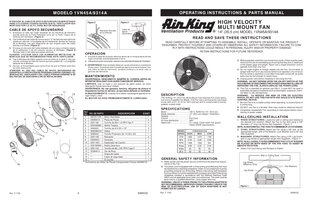
WALL/CEILING INSTALLATION
1.WOOD STRUCTURES: Locate the wall or ceiling stud nearest to the desired Fan location. Attach the Fan to the stud using a 3/8" diameter x 2" long Lag Screw (Not Supplied). (Figure 1)
NOTE: ALWAYS INSTALL THE YOKE TO A MINIMUM OF 2 X 4 STUDDING.
2.STEEL STRUCTURES: Attach the Fan using a 3/8" bolt of the appropriate length, with a Flat Washer, Lock Washer and a 3/8" Nut (Not Supplied).
3.MASONRY STRUCTURES: Attach Fan using a 3/8" Lag Screw, with a Lag Shield of appropriate length (Not Supplied). (Figure 1)
NOTE: IN ALL CASES, IT IS RECOMMENDED THAT A FLAT WASHER BE PLACED ON BOTH SIDES OF THE FAN YOKE TO ASSIST IN SMOOTH ROTATION.
4.Attach Pull Cord String and Pendant to Switch.
 Wall or Ceiling Stud
Lag Shield
(Masonry Only)
Flat Washers
Lag Screw 

Figure 1