2/2
Wiring diagram
REAR
Circuit 1
Wiring diagram(MAIN C.B)
![]()
![]()
![]() FRONT TU101
FRONT TU101
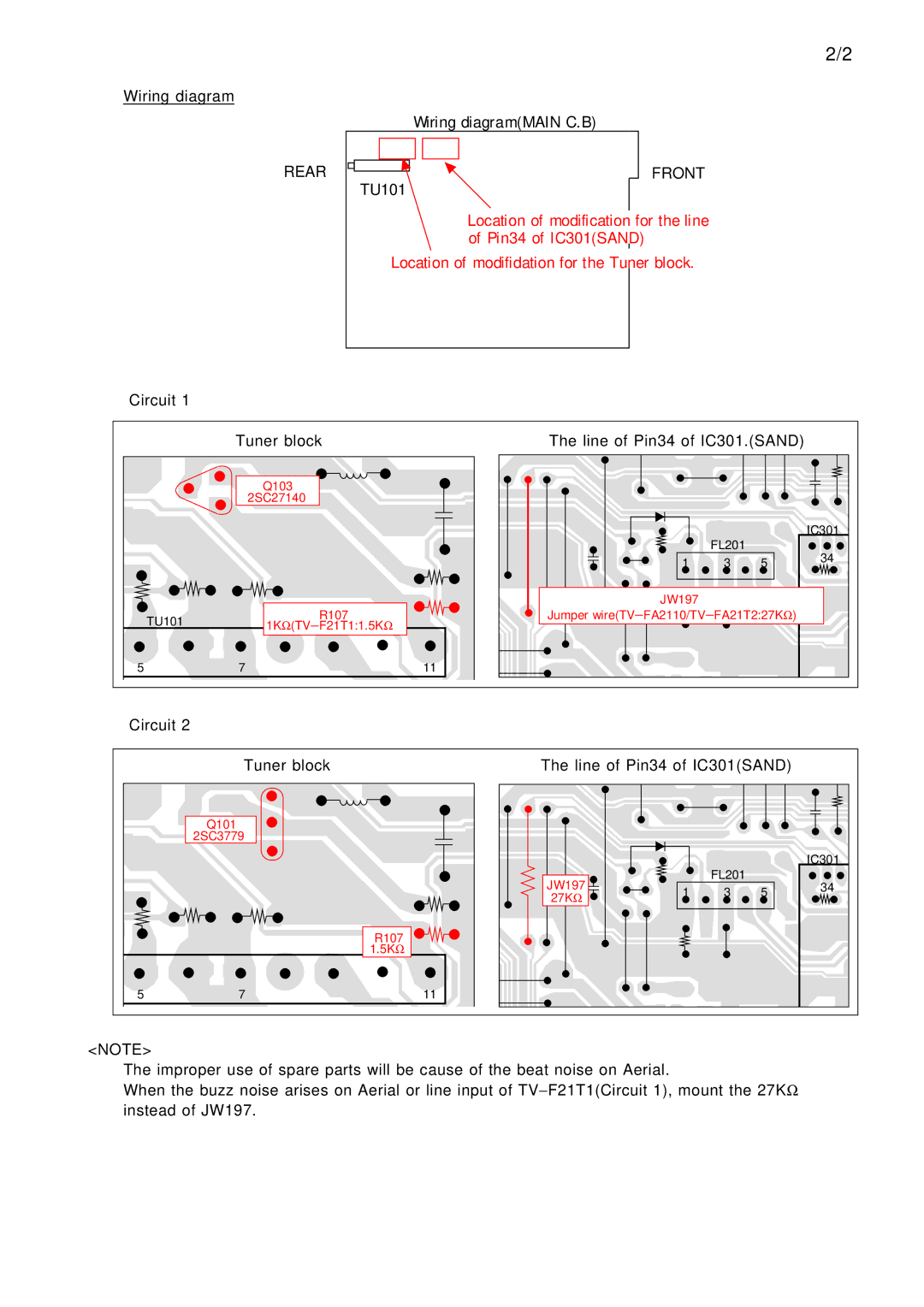
Location of modification for the line of Pin34 of IC301(SAND)
Location of modifidation for the Tuner block.
Tuner block
Q103
2SC27140
| TU101 | 1KΩ | R107 |
| (TV− F21T1:1.5KΩ | ||
5 | 7 |
| 11 |
The line of Pin34 of IC301.(SAND)
|
|
| IC301 | |
| FL201 |
| 34 | |
1 | 3 | 5 | ||
| ||||
JW197 |
|
|
| |
Jumper wire(TV− FA2110/TV− FA21T2:27KΩ ) |
| |||
Circuit 2
Tuner block
Q101
2SC3779
R107
1.5KΩ
5 | 7 | 11 |
The line of Pin34 of IC301(SAND)
|
|
|
| IC301 | |
JW197 |
| FL201 |
| 34 | |
1 | 3 | 5 | |||
27KΩ |
| ||||
|
|
|
|
<NOTE>
The improper use of spare parts will be cause of the beat noise on Aerial.
When the buzz noise arises on Aerial or line input of TV− F21T1(Circuit 1), mount the 27KΩ instead of JW197.
