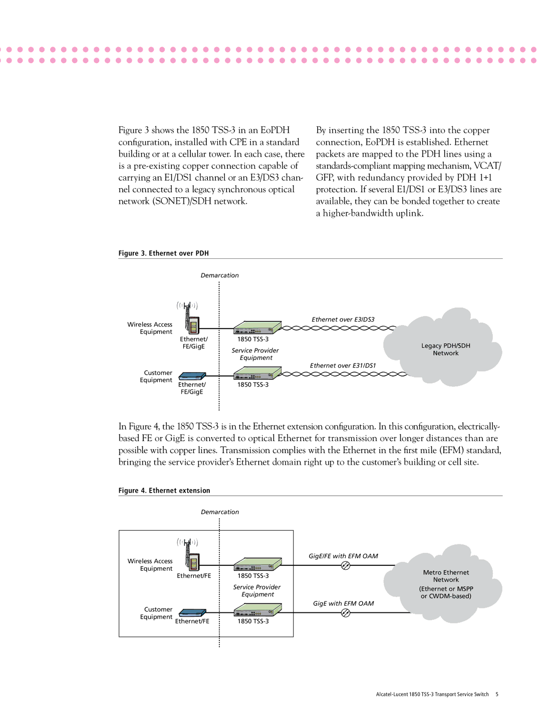
Figure 3 shows the 1850 TSS-3 in an EoPDH configuration, installed with CPE in a standard building or at a cellular tower. In each case, there is a pre-existing copper connection capable of carrying an E1/DS1 channel or an E3/DS3 chan- nel connected to a legacy synchronous optical
network (SONET)/SDH network.
By inserting the 1850
Figure 3. Ethernet over PDH
Demarcation
Wireless Access |
| Ethernet over E3/DS3 |
|
| |
Equipment |
|
|
Ethernet/ | 1850 | Legacy PDH/SDH |
FE/GigE | Service Provider | |
| Network | |
| Equipment | |
|
| |
Customer |
| Ethernet over E31/DS1 |
|
| |
Equipment Ethernet/ | 1850 |
|
FE/GigE |
|
|
In Figure 4, the 1850
Figure 4. Ethernet extension
Demarcation
Wireless Access |
| GigE/FE with EFM OAM | |
|
| ||
Equipment |
| Metro Ethernet | |
Ethernet/FE | 1850 | ||
Network | |||
| Service Provider | ||
| (Ethernet or MSPP | ||
| Equipment | or | |
Customer |
| GigE with EFM OAM | |
|
| ||
Equipment Ethernet/FE | 1850 |
|