NS-16T01FS specifications
Alloy Computer Products has made a significant impact in the field of networking with its NS-16T01FS switch. This compact and versatile device is designed specifically for small to medium-sized enterprises, helping them to manage their network more efficiently while maintaining high performance.The NS-16T01FS is a 16-port Fast Ethernet switch that provides essential networking features in a cost-effective package. Each of its 16 ports supports auto-sensing 10/100Mbps Ethernet connectivity, which ensures that devices can connect seamlessly without the need for configuration. This plug-and-play functionality allows for quick setup, enabling businesses to focus on their core operations rather than IT management.
One of its standout features is the non-blocking architecture, which allows all 16 ports to operate at maximum speed without interference. This means that businesses can experience reliable data transfer rates for tasks such as file sharing, video conferencing, and cloud computing, which are essential in today’s digital environment.
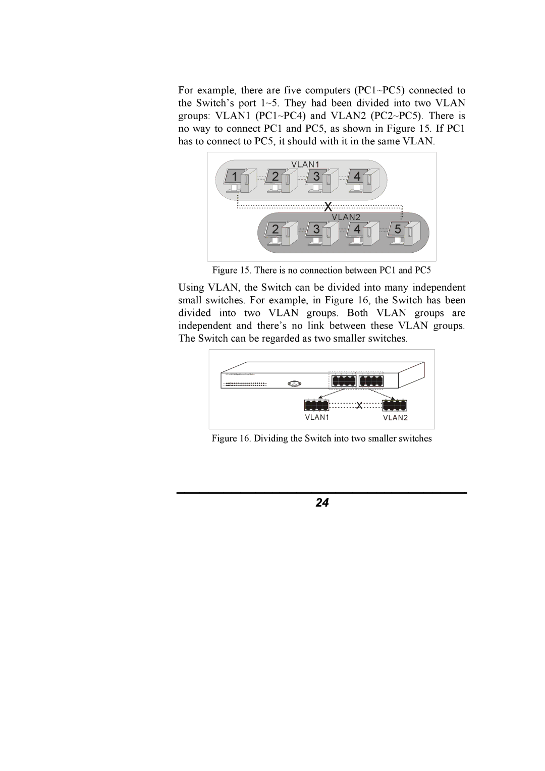
The NS-16T01FS is also equipped with advanced features such as IEEE 802.1d Spanning Tree Protocol (STP), helping to prevent network loops and ensuring stability in larger networks. Its ability to take advantage of Virtual LAN (VLAN) technology allows for the segmentation of network traffic, improving security and performance by reducing congestion and allowing better management of network resources.
Power over Ethernet (PoE) support is another notable aspect of the NS-16T01FS. With this capability, devices such as IP cameras, VoIP phones, and wireless access points can receive power through the switch, simplifying installations and reducing the need for additional electrical outlets.
Robust security features are also integrated into this switch. It supports port-based Network Access Control, ensuring that only authorized devices can connect to the network. This adds an essential layer of security to protect sensitive data from unauthorized access.
In conclusion, the Alloy Computer Products NS-16T01FS switch is a functional and reliable networking solution for small to medium-sized businesses. Its array of features, including high-speed connectivity, robust security protocols, and PoE support, make it an ideal choice for organizations looking to enhance their network performance without compromising on budget. With this switch in their arsenal, businesses can ensure seamless connectivity and efficient network management as they grow and expand in the digital landscape.

